MC10H107(2016) データシートの表示(PDF) - ON Semiconductor
部品番号
コンポーネント説明
一致するリスト
MC10H107 Datasheet PDF : 5 Pages
| |||
4
2
5
3
9
11
7
10
14
12
15
13
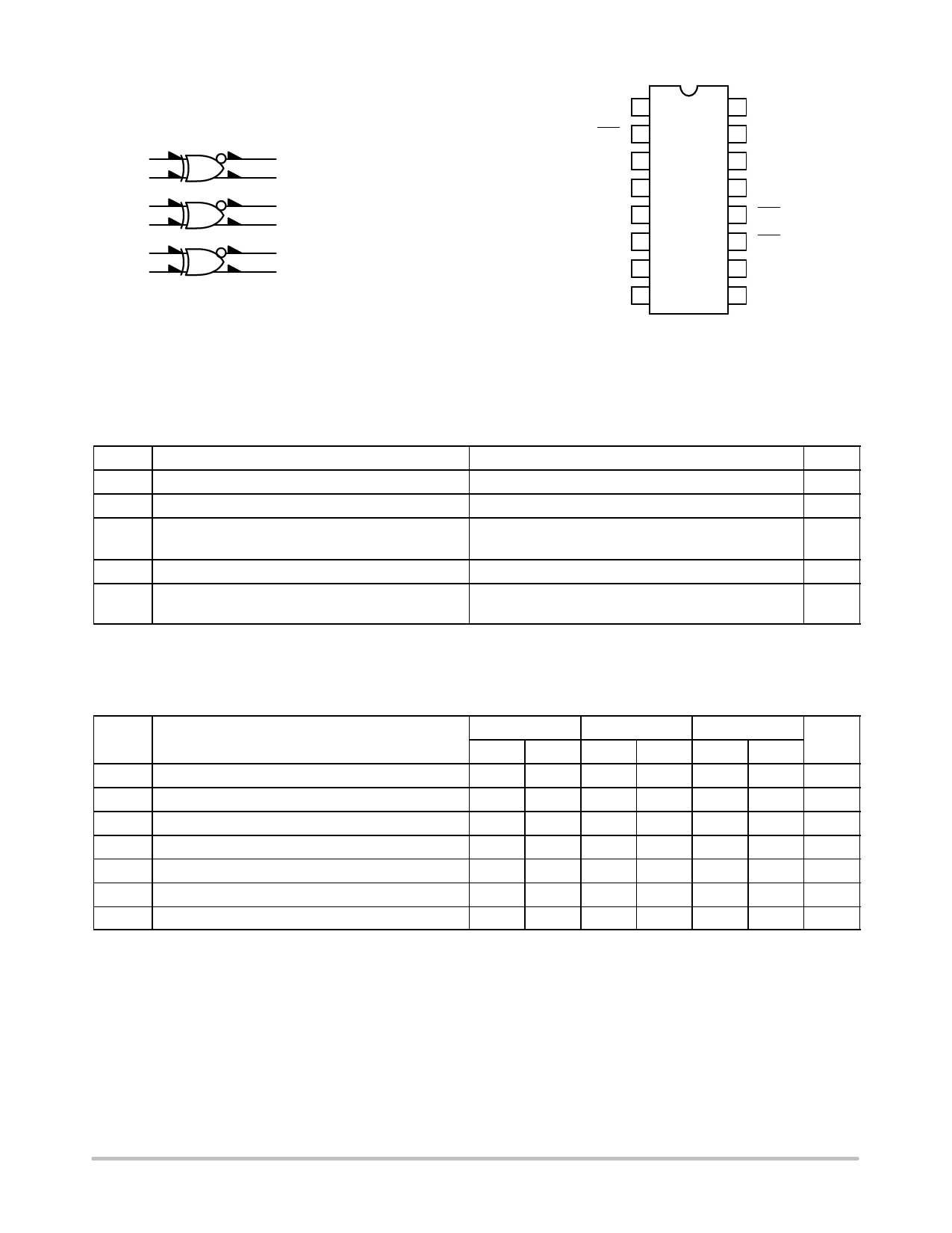
VCC1 = Pin 1
VCC2 = Pin 16
VEE = Pin 8
Figure 1. Logic Diagram
MC10H107
VCC1
1
Aout
2
Aout
3
Ain
4
Ain
5
*NC
6
Bin
7
VEE
8
16
VCC2
15
Cin
14
Cin
13
Cout
12
Cout
11
Bout
10
Bout
9
Bin
*NC = No Connection
Pin assignment is for Dual-in-Line Package.
Figure 2. Pin Assignment
Table 1. MAXIMUM RATINGS
Symbol
Characteristic
VEE Power Supply (VCC = 0)
VI
Input Voltage (VCC = 0)
Iout Output Current
Continuous
Surge
TA
Operating Temperature Range
Tstg Storage Temperature Range
Plastic
Ceramic
Rating
Unit
−8.0 to 0
Vdc
0 to VEE
Vdc
mA
50
100
0 to +75
°C
°C
−55 to +150
−55 to +165
Stresses exceeding those listed in the Maximum Ratings table may damage the device. If any of these limits are exceeded, device functionality
should not be assumed, damage may occur and reliability may be affected.
Table 2. ELECTRICAL CHARACTERISTICS (VEE = −5.2 V ±5%) (Note 1)
0°
25°
75°
Symbol
Characteristic
Min
Max
Min
Max
Min
Max
Unit
IE
Power Supply Current
IinH Input Current High
IinL Input Current Low
VOH High Output Voltage
VOL Low Output Voltage
VIH High Input Voltage
VIL Low Input Voltage
−
31
−
28
−
31
mA
−
425
−
265
−
265
mA
0.5
−
0.5
−
0.3
−
mA
−1.02 −0.84 −0.98 −0.81 −0.92 −0.735 Vdc
−1.95 −1.63 −1.95 −1.63 −1.95 −1.60 Vdc
−1.17 −0.84 −1.13 −0.81 −1.07 −0.735 Vdc
−1.95 −1.48 −1.95 −1.48 −1.95 −1.45 Vdc
1. Each MECL 10H series circuit has been designed to meet the dc specifications shown in the test table, after thermal equilibrium has been
established. The circuit is in a test socket or mounted on a printed circuit board and transverse air flow greater than 500 linear fpm is
maintained. Outputs are terminated through a 50 W resistor to −2.0 V.
www.onsemi.com
2
Share Link: 