MAXQ2000-KIT データシートの表示(PDF) - Maxim Integrated
部品番号
コンポーネント説明
一致するリスト
MAXQ2000-KIT Datasheet PDF : 15 Pages
| |||
MAXQ2000 Evaluation Kit
Internal Power Rails
The MAXQ2000 EV kit board generates three internal
power rails from the DC input power supply (from J1 or
the serial-to-JTAG board). Each of these supplies may
be used to support up to 100mA of additional circuitry
in the prototyping area. (Note: Test point TP1 is board
ground.)
• The adjustable power supply, which can be mea-
sured at test point TP2, provides an adjustable volt-
age between +1.8V and +3.6V. The level of this
supply can be adjusted manually by turning poten-
tiometer R2 with a screwdriver.
• The 3.6V fixed power supply can be measured at
test point TP3. This voltage level can be used for
VDDIO or VLCD, but not VDD.
• The 2.5V fixed power supply can be measured at
test point TP4. This voltage level can be used for
VDDIO, VLCD, or VDD.
Table 1 shows how the jumpers connect the MAXQ2000
power rails to the on-board power supplies.
Using the LCD Display
To use the LCD daughterboard, it should be installed on
the J3 connector of the MAXQ2000 EV kit board. Pin 1
on J3 should line up with pin 1 of the LCD daughter-
board J1 connector. Note that when the LCD daughter-
board is installed correctly, it hangs off the top edge of
the MAXQ2000 EV kit board. When the LCD display is in
use, VLCD should be connected to +3.6V.
The LCD display on the LCD daughterboard is a static,
4-1/2 digit display. Figure 4 shows how the segments
are mapped. If the LCD display is not needed, it can be
removed to free up port pins P0.0–P0.7, P1.0–P1.7,
P2.0–P2.7, and P3.0–P3.7 for other uses.
Additional Hardware Features
Most of the additional hardware on the MAXQ2000 EV
kit board, such as the serial port, the MAX1407, and the
1-Wire interface, can be enabled or disabled by setting
jumpers or DIP switches. Disabling unused hardware
frees up the associated port pins for other uses.
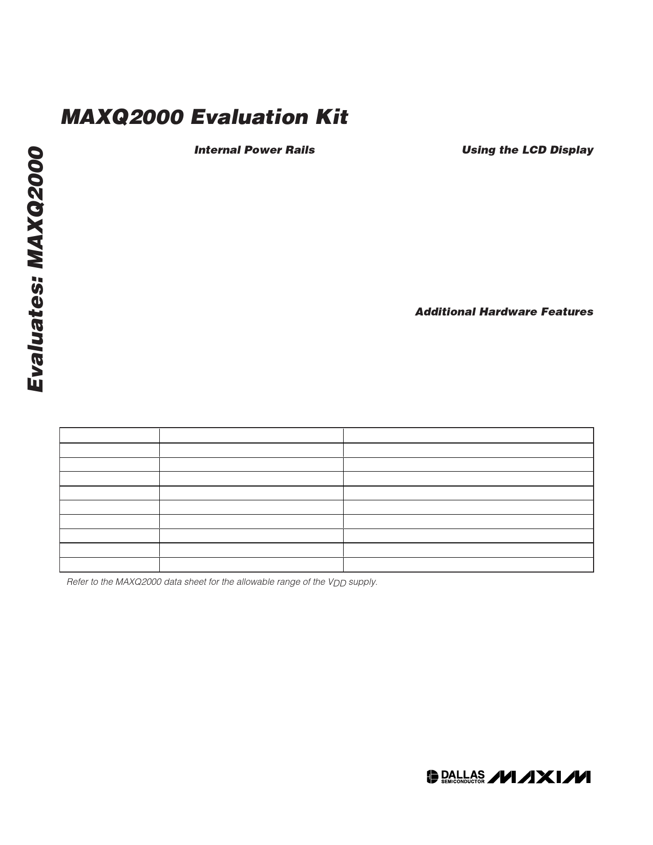
Table 1. Power-Supply Jumper Settings
JUMPER
SETTING
EFFECT
JU1
(No jumper)
VDD is floating (drive from bench supply)*
JU1
Pins 1 and 2 connected
VDD is driven by +2.5V fixed supply
JU1
Pins 2 and 3 connected
VDD is driven by adjustable supply*
JU2
(No jumper)
VDDIO is floating (drive from bench supply)
JU2
Pins 1 and 2 connected
VDDIO is driven by +3.6V fixed supply
JU2
Pins 2 and 3 connected
VDDIO is driven by adjustable supply
JU3
(No jumper)
VLCD is floating (drive from bench supply)
JU3
Pins 1 and 2 connected
VLCD is driven by +3.6V fixed supply
JU3
Pins 2 and 3 connected
VLCD is driven by adjustable supply
* Refer to the MAXQ2000 data sheet for the allowable range of the VDD supply.
4 _____________________________________________________________________
Share Link: 