MASW-002102-13580 データシートの表示(PDF) - M/A-COM Technology Solutions, Inc.
部品番号
コンポーネント説明
一致するリスト
MASW-002102-13580
M/A-COM Technology Solutions, Inc.

MASW-002102-13580 Datasheet PDF : 7 Pages
| |||
MASW-002102-13580
MASW-003102-13590
HMIC™ Silicon PIN Diode Switches
with Integrated Bias Network
Rev. V5
Wire/Ribbon and Die Attachment Recommendations
Wire Bonding
Thermosonic wedge wire bonding using 0.00025” x 0.003” ribbon or 0.001” diameter gold wire is
recommended. A heat stage temperature of 150oC and a force of 18 to 22 grams should be used. Ultrasonic
energy should be adjusted to the minimum required to achieve a good bond. RF bond wires should be kept as
short and straight as possible.
Chip Mounting
The HMIC switches have Ti-Pt-Au back metal. They can be die mounted with a gold-tin eutectic solder
preform or conductive epoxy. Mounting surface must be clean and flat.
*Note: This device utilizes a process step designed to have minimal to non-existent burring around the
perimeter of the die.
Eutectic Die Attachment: An 80/20, gold-tin, eutectic solder preform is recommended with a work surface
temperature of 255oC and a tool tip temperature of 265oC. When hot gas is applied, the tool tip temperature
should be 290oC. The chip should not be exposed to temperatures greater than 320oC for more than
20 seconds. No more than three seconds should be required for attachment. Solders containing tin should not
be used.
Epoxy Die Attachment: A minimum amount of epoxy should be used. A thin epoxy fillet should be visible
around the perimeter of the chip after placement. Cure epoxy per manufacturer’s schedule (typically 125-
150oC).
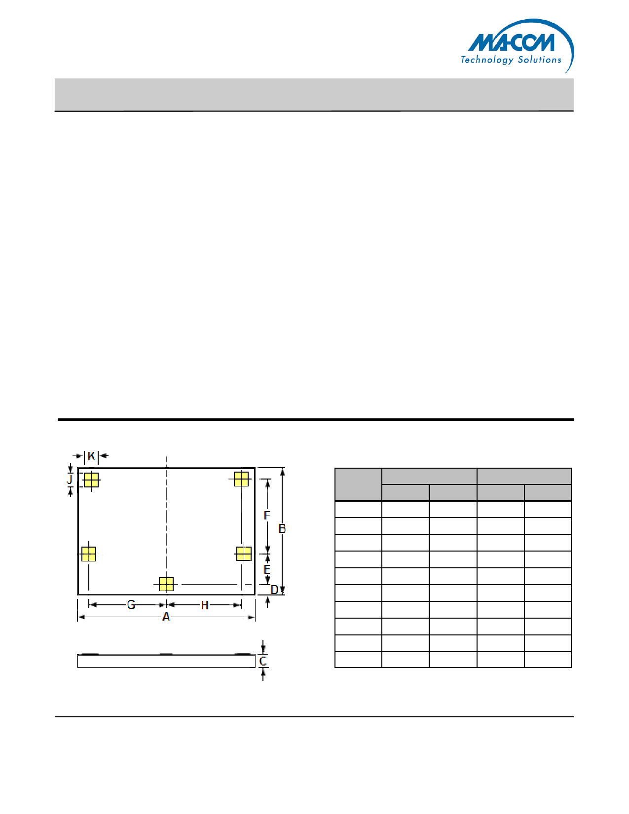
MASW-002102-13580 Chip Outline Drawing1,2
INCHES
MILLIMETERS
DIM
MIN
MAX
MIN
MAX
A
0.066
0.070
1.680
1.780
B
0.048
0.052
1.230
1.330
C
0.004
0.006
0.100
0.150
D
0.004
0.006
0.090
0.140
E
0.012
0.013
0.292
0.317
F
0.029
0.030
0.735
0.760
G
0.030
0.031
0.766
0.791
H
0.029
0.030
0.732
0.757
J
0.005
REF.
0.129
REF.
K
0.005
REF.
0.129
REF.
Notes:
1. Topside and backside metallization is gold, 2.5um thick typical.
2. Yellow areas indicate wire bonding pads
6
ADVANCED: Data Sheets contain information regarding a product M/A-COM Technology Solutions • North America Tel: 800.366.2266 • Europe Tel: +353.21.244.6400
is considering for development. Performance is based on target specifications, simulated results,
and/or prototype measurements. Commitment to develop is not guaranteed.
PRELIMINARY: Data Sheets contain information regarding a product M/A-COM Technology
• India Tel: +91.80.43537383
• China Tel: +86.21.2407.1588
Visit www.macomtech.com for additional data sheets and product information.
Solutions has under development. Performance is based on engineering tests. Specifications are
typical. Mechanical outline has been fixed. Engineering samples and/or test data may be available. M/A-COM Technology Solutions Inc. and its affiliates reserve the right to make
Commitment to produce in volume is not guaranteed.
changes to the product(s) or information contained herein without notice.
Share Link: