MA739 データシートの表示(PDF) - Panasonic Corporation
部品番号
コンポーネント説明
一致するリスト
MA739 Datasheet PDF : 3 Pages
| |||
This product complies with the RoHS Directive (EU 2002/95/EC).
Schottky Barrier Diodes (SBD)
MA2Q739 (MA739)
Silicon epitaxial planar type
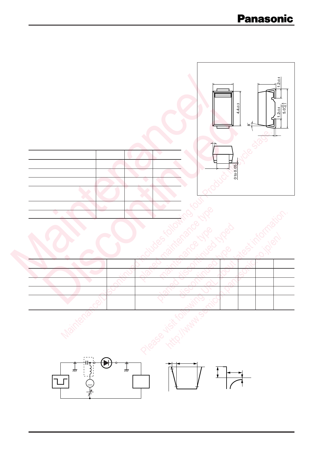
Unit: mm
For high frequency rectification
■ Features
• Forward current (Average) IF(AV) = 0.7 A rectification is possible
/ • Reverse voltage VR = 90 V is guaranteed
• Automatic insertion with the emboss taping is possible
ce tage. ■ Absolute Maximum Ratings Ta = 25°C
n d le s Parameter
Symbol Rating
Unit
a e cyc Reverse voltage
VR
90
V
life Maximum peak reverse voltage VRM
90
V
ct Forward current (Average) *1
IF(AV)
0.7
A
n u rodu Non-repetitive peak forward
IFSM
10
A
P surge current *2
te tin ur Junctiontemperature
g fo e . Storage temperature
Tj
−40 to +125
°C
Tstg
−40 to +125
°C
win typ tion Note) *1: Mounted on the printed circuit board (glass epoxy boad)
in n follo ance pe ed rma *2: Thepeak-to-peakvalueinonecycleof50Hzsinewave(non-repetitive)
2.5±0.3
2
2.15±0.3
1
8˚
0.25+–00..015
1.4±0.2
1 : Anode
2 : Cathode
NMiniP2-J1 Package
Marking Symbol: PE
a coed inclueddesmaintteennancettiynued ttyyppe test info.jp/en/ ■ Electrical Characteristics Ta = 25°C ± 3°C
u n in on d t la .co Parameter
Symbol
Conditions
Min Typ Max Unit
M is tin la a isc ue ou nic Forward voltage
on p m d d ntin ab aso Reverse current
isc ne co RL an Terminal capacitance
e/D pla dis ing U icon.p Reverse recovery time *
VF
IF = 0.7 A
IR
VR = 90 V
Ct
VR = 10 V, f = 1 MHz
trr
IF = IR = 100 mA
Irr = 0.1 IR , RL = 100 Ω
0.8
V
1.0 mA
50
pF
100
ns
Danc llow em Note) 1. Measuring methods are based on JAPANESE INDUSTRIAL STANDARD JIS C 7031 measuring methods for diodes.
ten fo .s 2. This product is sensitive to electric shock (static electricity, etc.). Due attention must be paid on the charge of a human body
in isit ww and the leakage of current from the operating equipment.
Ma e v ://w 3. Absolute frequency of input and output is 10 MHz
as ttp 4. *: trr measurement circuit
Ple h Bias Application Unit (N-50BU)
Input Pulse
Output Pulse
tr
tp
t
10%
IF
trr
t
A
Pulse Generator
(PG-10N)
Rs = 50 Ω
Wave Form Analyzer
(SAS-8130)
Ri = 50 Ω
VR
90%
tp = 2 µs
tr = 0.35 ns
δ = 0.05
Irr = 0.1 IR
IF = 100 mA
IR = 100 mA
RL = 100 Ω
Publication date: April 2004
Note) The part number in the parenthesis shows conventional part number.
SKH00022BED
1
Share Link: 