MA732 データシートの表示(PDF) - Panasonic Corporation
部品番号
コンポーネント説明
一致するリスト
MA732 Datasheet PDF : 3 Pages
| |||
This product complies with the RoHS Directive (EU 2002/95/EC).
Schottky Barrier Diodes (SBD)
MA2J732 (MA732)
Silicon epitaxial planar type
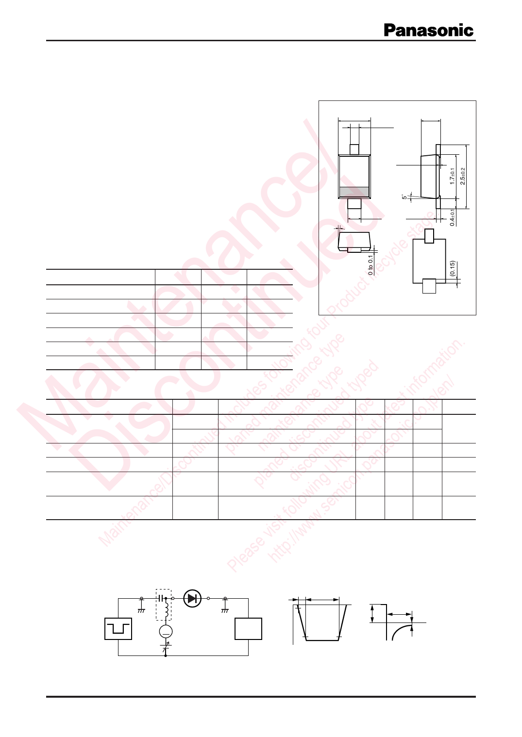
Unit: mm
For switching
For wave detection
■ Features
/ • Low forward voltage VF, optimum for low voltage rectification
• Low VF type of MA3X704A (MA704A)
e • Optimum for high frequency rectification because of its short re-
e. verse recovery time trr
1.25±0.1
0.35±0.1
0.7±0.1
1
0 to 0.1
2
0.5±0.1
5˚
0.16+–00..016
nc d ycle stag ■ Absolute Maximum Ratings Ta = 25°C
a e lifec Parameter
Symbol Rating
Unit
ct Reverse voltage
VR
30
V
n u rodu Maximum peak reverse voltage VRM
30
V
P Peak forward current
IFM
150
mA
te tin four Forwardcurrent
IF
30
mA
ing type n. Junction temperature
Tj
125
°C
in n llow e tio Storage temperature
Tstg
−55 to +125
°C
1: Anode
2: Cathode
EIAJ: SC-76
SMini2-F1 Package
Marking Symbol: 2C
a o ludes fointenance type typed informan/ ■ Electrical Characteristics Ta = 25°C ± 3°C
c ed inc ed ma tenanc tinued type test .jp/e Parameter
Symbol
Conditions
Min Typ Max Unit
u n in on d t la .co Forward voltage
M is tin pla ma disc tinue abou sonic Reverse current
iscon ned con RL ana Terminal capacitance
/D pla dis g U n.p Reverse recovery time *
Dtenance followin.semico Detection efficiency
VF1
IF = 1 mA
VF2
IF = 30 mA
IR
VR = 30 V
Ct
VR = 1 V, f = 1 MHz
trr
IF = IR = 10 mA
Irr = 1 mA, RL = 100 Ω
η
VIN = 3 V(peak) , f = 30 MHz
RL = 3.9 kΩ, CL = 10 pF
0.3
V
1.0
30
µA
1.5
pF
1.0
ns
65
%
in it w Note) 1. Measuring methods are based on JAPANESE INDUSTRIAL STANDARD JIS C 7031 measuring methods for diodes.
Ma e vis ://ww 2. This product is sensitive to electric shock (static electricity, etc.). Due attention must be paid on the charge of a human body
as ttp and the leakage of current from the operating equipment.
Ple h 3. Absolute frequency of input and output is 2 GHz.
4. *: trr measurement circuit
Bias Application Unit (N-50BU)
Input Pulse
Output Pulse
tr
tp
10%
t
IF
trr
t
A
Pulse Generator
(PG-10N)
Rs = 50 Ω
Wave Form Analyzer
(SAS-8130)
VR
90%
tp = 2 µs
tr = 0.35 ns
δ = 0.05
Irr = 1 mA
IF = 10 mA
IR = 10 mA
RL = 100 Ω
Ri = 50 Ω
Note) The part number in the parenthesis shows conventional part number.
Publication date: April 2004
SKH00016BED
1
Share Link: 