M54HC11D1 データシートの表示(PDF) - STMicroelectronics
部品番号
コンポーネント説明
一致するリスト
M54HC11D1 Datasheet PDF : 8 Pages
| |||
M54HC11
AC ELECTRICAL CHARACTERISTICS (CL = 50 pF, Input tr = tf = 6ns)
Test Condition
Value
Symbol
Parameter
VCC
(V)
tTLH tTHL Output Transition 2.0
Time
4.5
6.0
tPLH tPHL Propagation Delay 2.0
Time
4.5
6.0
TA = 25°C
-40 to 85°C -55 to 125°C Unit
Min. Typ. Max. Min. Max. Min. Max.
30 75
8 15
7 13
40 85
10 17
9 14
95
110
19
22 ns
16
19
105
130
21
26 ns
18
22
CAPACITIVE CHARACTERISTICS
Test Condition
Value
Symbol
Parameter
VCC
(V)
TA = 25°C
-40 to 85°C -55 to 125°C Unit
Min. Typ. Max. Min. Max. Min. Max.
CIN Input Capacitance 5.0
5 10
10
10 pF
CPD Power Dissipation
Capacitance (note 5.0
26
pF
1)
1) CPD is defined as the value of the IC’s internal equivalent capacitance which is calculated from the operating current consumption without
load. (Refer to Test Circuit). Average operating current can be obtained by the following equation. ICC(opr) = CPD x VCC x fIN + ICC/3 (per gate)
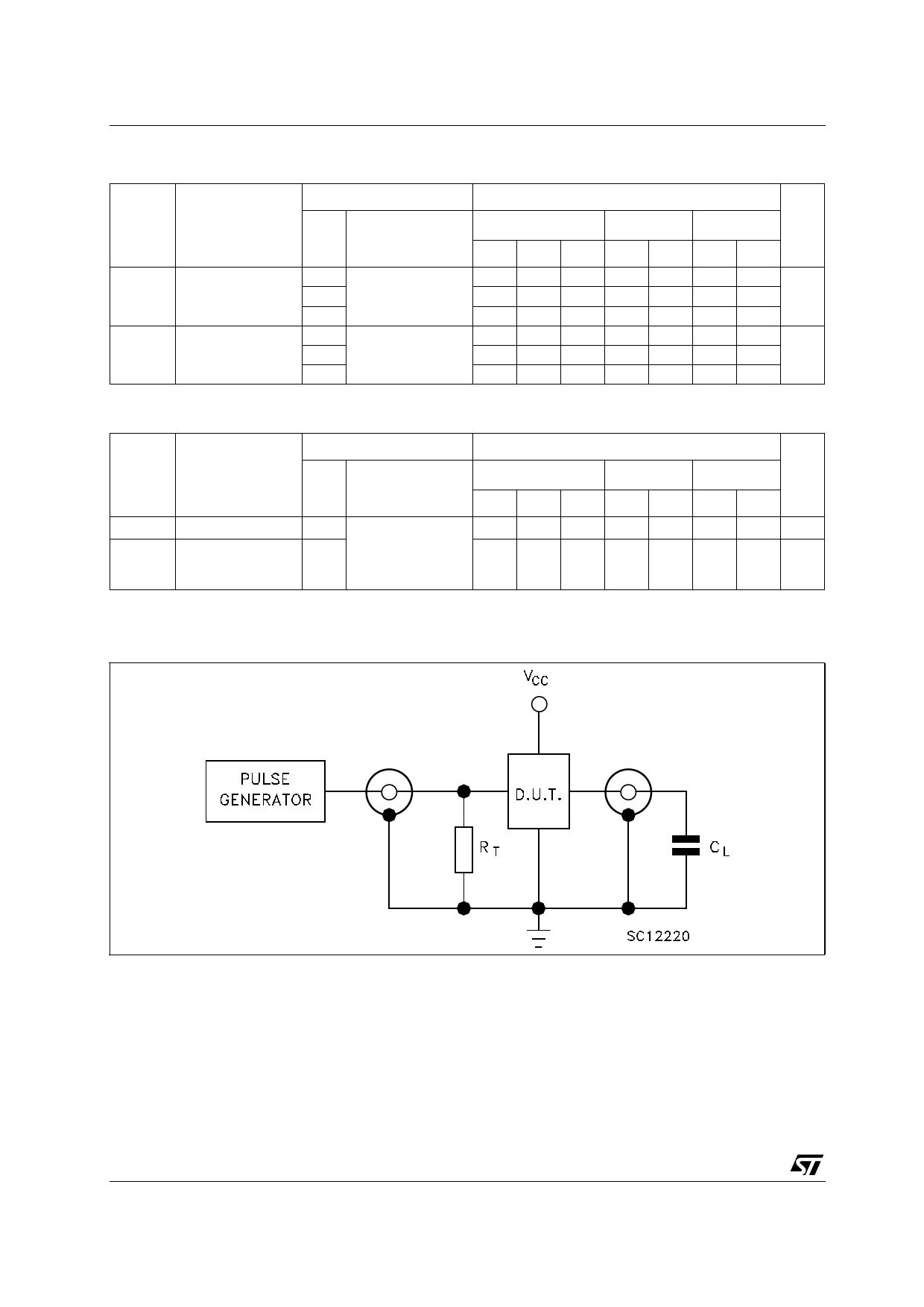
TEST CIRCUIT
CL = 50pF or equivalent (includes jig and probe capacitance)
RT = ZOUT of pulse generator (typically 50Ω)
4/8
Share Link: 