LIS3L02AQ3 データシートの表示(PDF) - STMicroelectronics
部品番号
コンポーネント説明
一致するリスト
LIS3L02AQ3 Datasheet PDF : 13 Pages
| |||
LIS3L02AQ3
be compatible with the external world.
The signals of the sensing element are multiplexed and fed into a low-noise capacitive charge amplifier that im-
plements a Correlated Double Sampling system (CDS) at its output to cancel the offset and the 1/f noise. The
output signal is de-multiplexed and transferred to three different S&Hs, one for each channel and made avail-
able to the outside.
The low noise input amplifier operates at 200 kHz while the three S&Hs operate at a sampling frequency of 66
kHz. This allows a large oversampling ratio, which leads to in-band noise reduction and to an accurate output
waveform.
All the analog parameters (zero-g level, sensitivity and self-test) are ratiometric to the supply voltage. Increasing
or decreasing the supply voltage, the sensitivity and the offset will increase or decrease almost linearly. The self
test voltage change varies cubically with the supply voltage
4.3 Factory calibration
The IC interface is factory calibrated for sensitivity (So) and Zero-g level (Voff).
The trimming values are stored inside the device by a non volatile structure. Any time the device is turned on,
the trimming parameters are downloaded into the registers to be employed during the normal operation. This
allows the user to employ the device without further calibration.
5 Application Hints
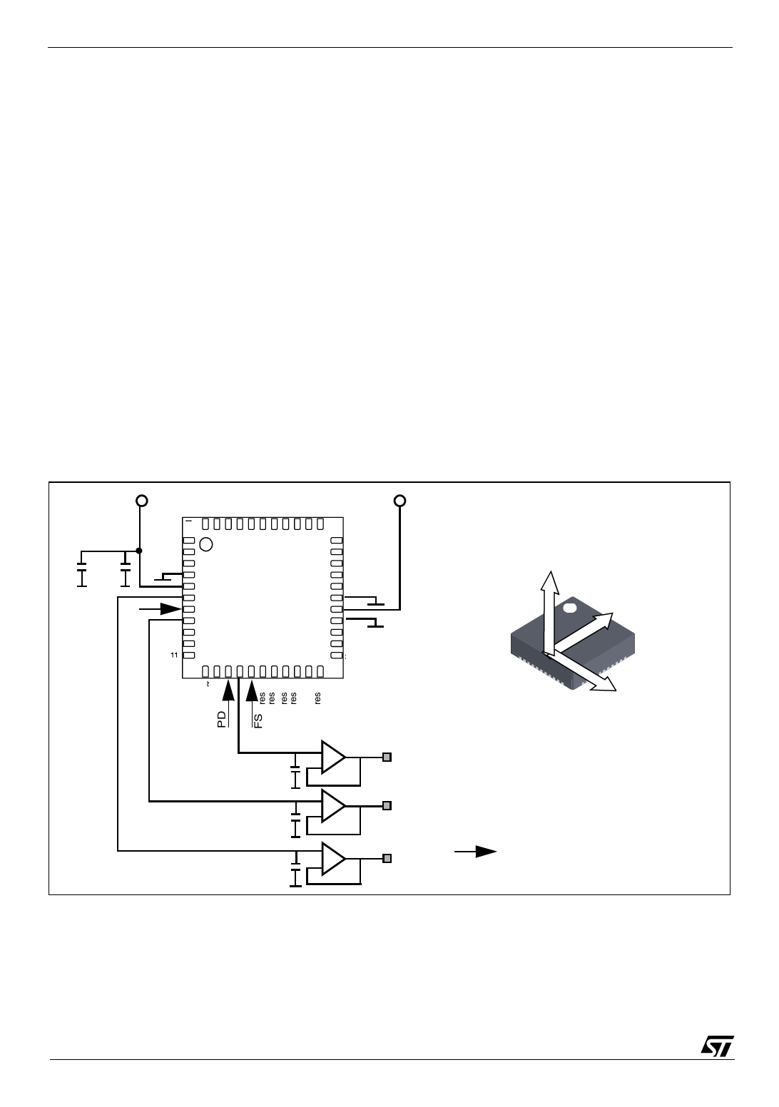
Figure 4. LIS3L02AQ3 Electrical Connection
Vdd
44
Vdd
34
10µF 100nF
GND GND
1
GND
ST
LIS3L02AQ3
(top view)
33
GND
GND
23res
12
22
Z
1
Y
X
11
Optional
Vout Z
Cload z
Cload x
Optional
Vout X
Cload y
Optional
Vout Y
DIRECTION OF THE
DETECTABLE
ACCELERATIONS
Digital signals
Power supply decoupling capacitors (100nF ceramic or polyester + 10µF Aluminum) should be placed as near
as possible to the device (common design practice).
The LIS3L02AQ3 allows to band limit Voutx, Vouty and Voutz through the use of external capacitors. The re-
commended frequency range spans from DC up to 1.5 KHz. In particular, capacitors must be added at output
pins to implement low-pass filtering for antialiasing and noise reduction. The equation for the cut-off frequency
6/13
Share Link: 