IT1 データシートの表示(PDF) - HIROSE ELECTRIC
部品番号
コンポーネント説明
一致するリスト
IT1 Datasheet PDF : 17 Pages
| |||
The product information in this catalog is for reference only. Please request the Engineering Drawing for the most current and accurate design information.
All non-RoHISTp1roSduectrsiehsav●e HbeiegnhdisScopnetineuded,, Morawtilcl bheeddis-cIomntipnueedd saononc.ePl,eaPsae rcahelclek lthBe opraordduc-ttsos-tabtousaorndthCe HoirnonseewcetbosirteSRyoHsStseemarch at www.hirose-connectors.com, or contact your Hirose sales representative.
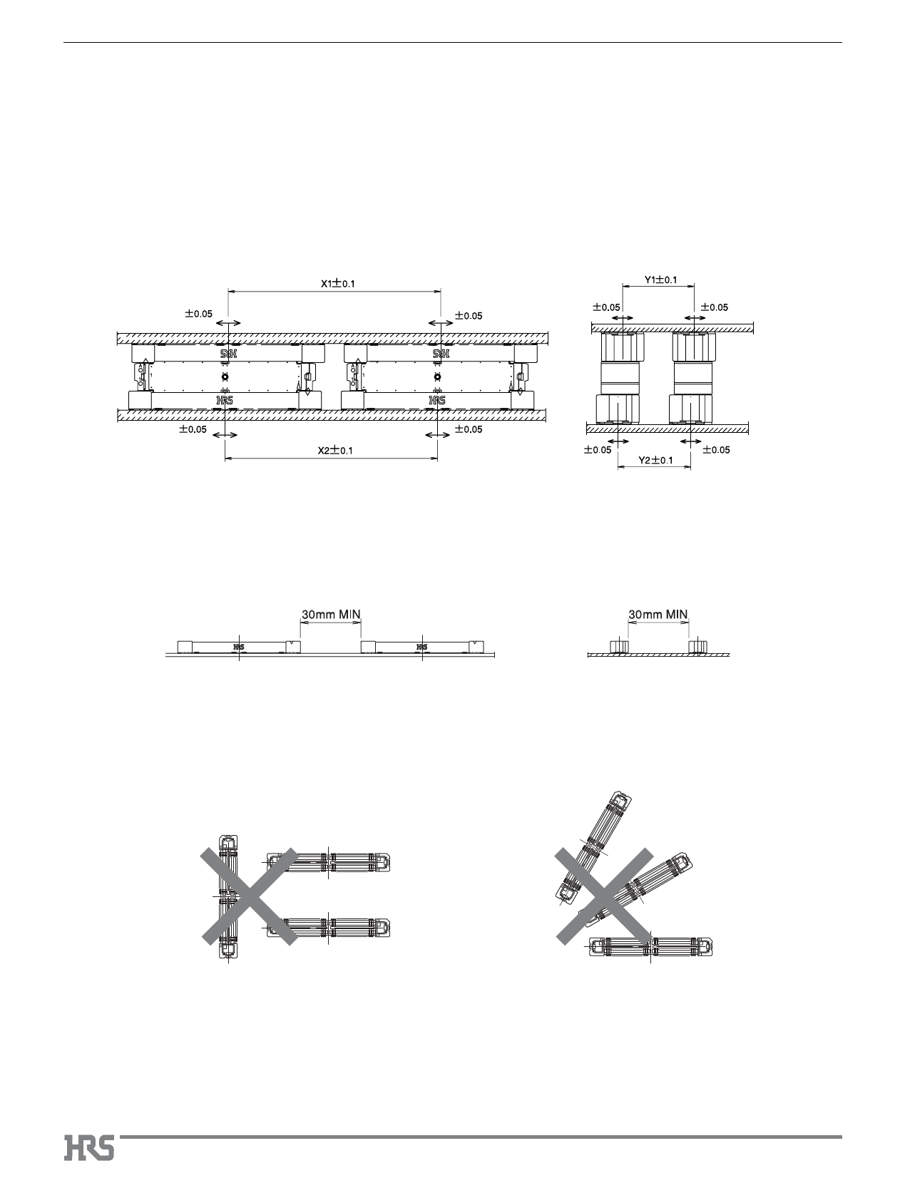
7. Precautions When Mounting Multiple Connectors
Note: Observe the requirements as listed in paragraph 7-1 and 7-2.
The mating/un-mating forces will increase with use of multiple assemblies. It is recommended that a dedicated tooling is used for
mating / un-mating of multiple connector assemblies in a single operation.
7-1 Allowable Amount of Misalignment
Maximum allowable misalignment in X and Y directions is ±0.2 mm total.
Refer to the drawings below.
Length Orientation
X1-X2= +-0.2
Width Orientation
Y1-Y2= +- 0.2
7-2 Recommended Connector Placement
It is recommended to leave min. of 30 mm space between the adjacent connector assemblies.
7-3 Examples of Prohibited Placement Positions
To assure reliability of solder joints and mating/ un-mating without damage,
DO NOT PLACE MULTIPLE CONNECTORS as illustrated below.
A310
Share Link: 