MM1053 データシートの表示(PDF) - Mitsumi
部品番号
コンポーネント説明
一致するリスト
MM1053 Datasheet PDF : 6 Pages
| |||
MITSUMI
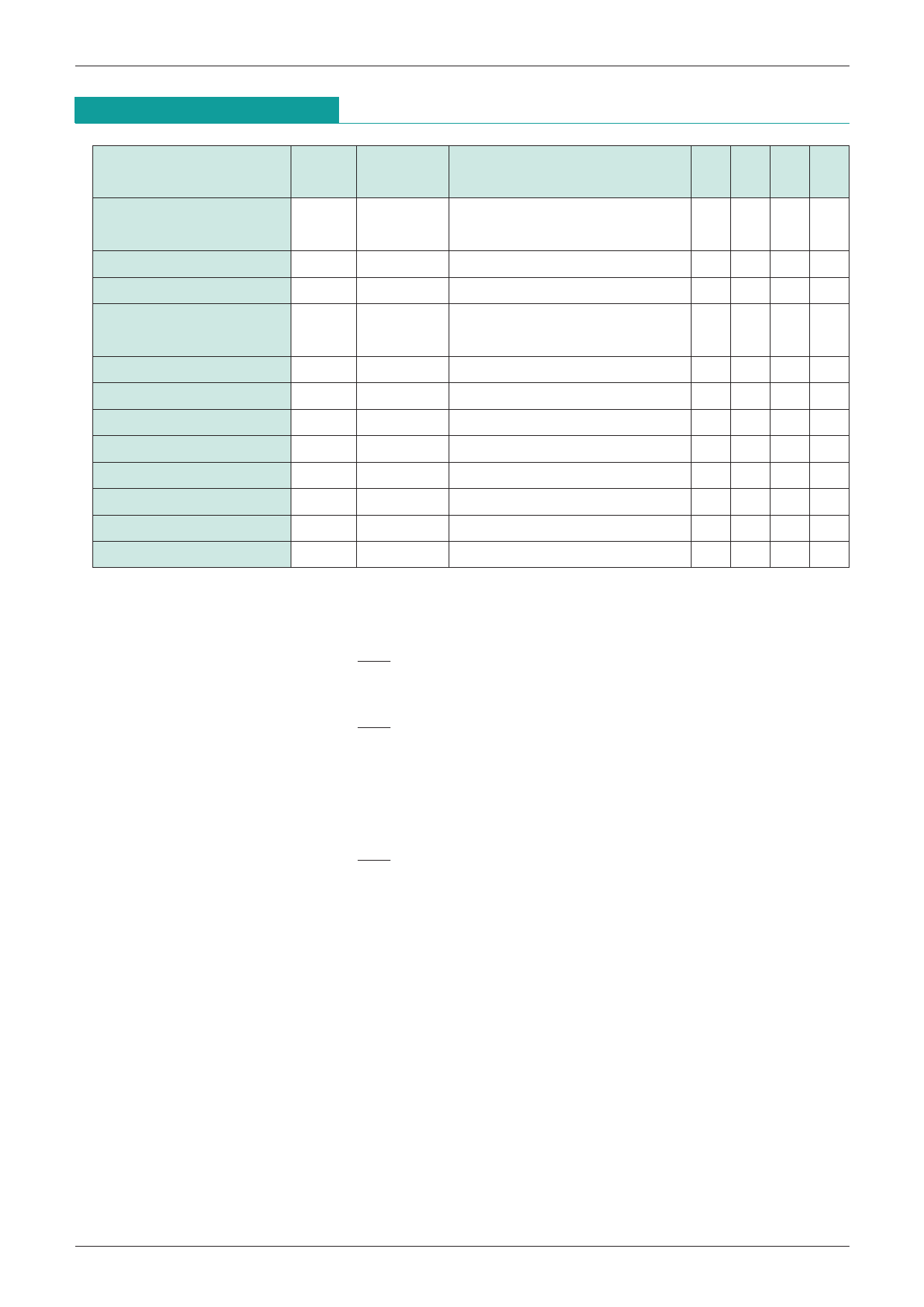
4-Input Video Switch (no clamp) MM1053
Electrical Characteristics (Except where noted otherwise, Ta=25°C, VCC=5.0V)
Item
Measurement
Symbol
conditions
Measurement conditions
Min. Typ. Max. Units
Operating power supply
VCC
VCC
voltage range
4.75 5.0 13.0 V
Consumption current
Id
VCC
7.0 11.0 mA
Voltage gain
GV
Frequency characteristic FC
Differential gain
DG
TP3
* SG : Sine wave 2VP-P, 0.1MHz 1 -0.5 0 0.5 dB
SG : Sine wave 2VP-P
TP3
-1 0 1 dB
* 10MHz/0.1MHz 1
TP3
SG : Staircase wave 2VP-P, APL=10, 50, 90%
03%
Differential phase
DP
TP3
SG : Staircase wave 2VP-P, APL=10, 50, 90%
0 3 deg
Output offset voltage
Voff
TP2
100 mV
Crosstalk
Switching voltage 1
Switching voltage 2
Input impedance
CT
VTH1
VTH2
RI
TP3
* SG : Sine wave 2VP-P, 4.43MHz 2
-65 -55 dB
TP4
* SG : Sine wave 2VP-P, 0.1MHz 3 0.7 1.4 2.1 V
TP5
* SG : Sine wave 2VP-P, 0.1MHz 3 0.7 1.4 2.1 V
TP3
15
kΩ
Output impedance
RO
TP3
15
Ω
*1 Voltage gain GV, frequency response FC
If input at TP1 for 0.1MHz sine wave input is V1, and output at TP3 is V2, and output for 10MHz
input is V3, then :
V2
GV=20LOG
V1
V3
FC=20LOG
V2
*2 Crosstalk CT
If input at TP1 for 4.43MHz sine wave input is V4, and output at TP3 is V5, then :
V5
CT=20LOG
V4
*3 Switching voltage VTH1, VTH2
TP4 level is VTH1 when TP4 DC level is changed by the external power supply and the output
signal switches. TP5 level is VTH2 when TP5 DC level is changed by the external power supply
and the output signal switches.
Share Link: 