RF2643 データシートの表示(PDF) - RF Micro Devices
部品番号
コンポーネント説明
一致するリスト
RF2643 Datasheet PDF : 16 Pages
| |||
Preliminary
RF2643
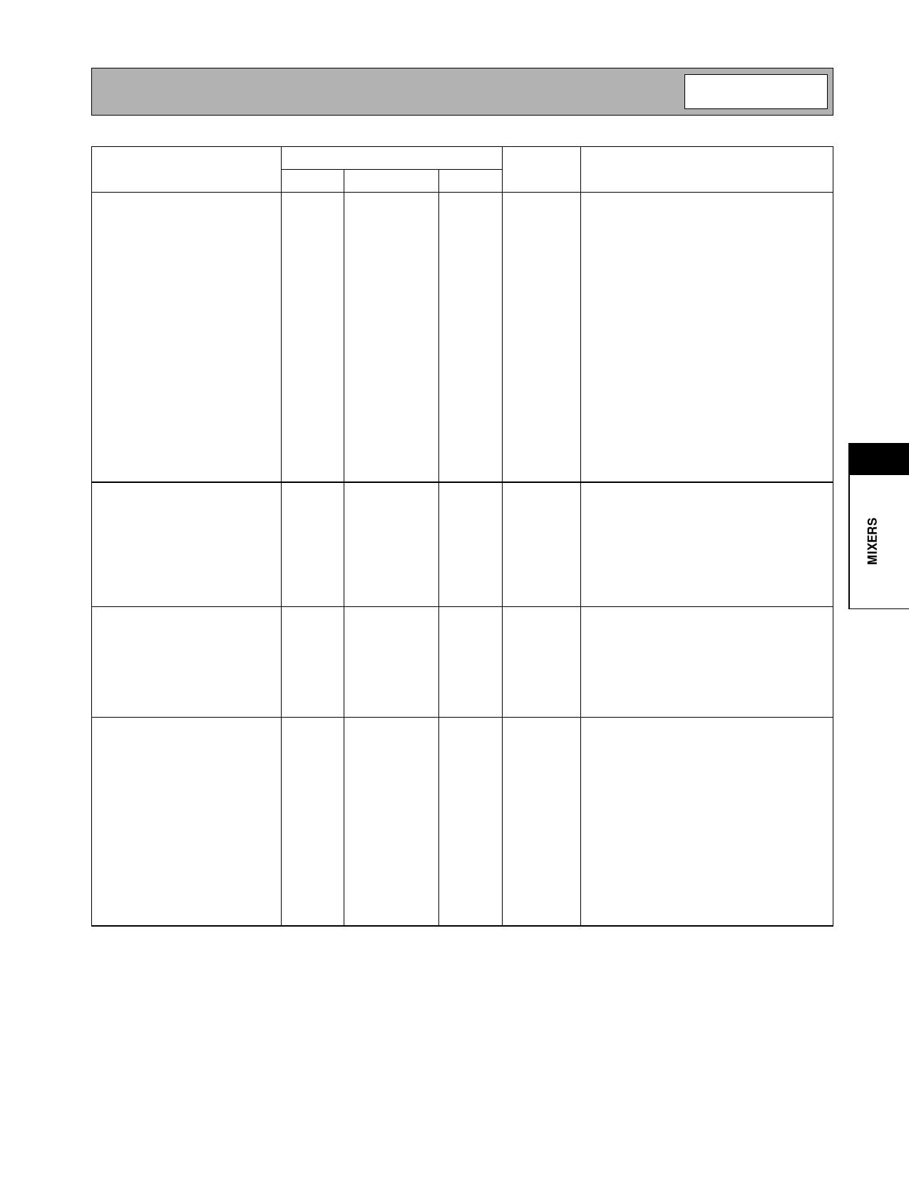
Parameter
Specification
Unit
Min.
Typ.
Max.
Condition
Amplifiers/Attenuators
Unless stated otherwise, all data in this sec-
Both Bands
tion is for both Cellular and PCS bands.
T=25°C, VCC=2.75V.
Gain Control Range
17
20
dB
Gain Control Voltage
0.8
1.9
V
Gain Control Slope
15
35
dB/V
Input Impedance
Single-Ended
50
Ω
Input Return Loss
10
dB
Single-Ended
Output Impedance
Single-Ended
50
Ω
Output Return Loss
10
dB
Single-Ended
RF Output Collector Current
10
mA
Consumption
Upconverter Output to
35
40
dB
Any load.
6
Amplifier Input
Cellular Band
RF Frequency Range
824
849
MHz
Maximum Gain
5
7
9
dB
Amplifier + Attenuator
Noise Figure at Maximum Gain
2.5
dB
Amplifier + Attenuator
Noise Figure Increase with
0.75
dB/dB
Attenuation
Input IP3 (Linearity)
-1
1
dBm
@ all gain levels
See Note 1 (end of parameter table).
PCS Band
RF Frequency Range
1850
1910
MHz
Maximum Gain
4
6
8
dB
Amplifier + Attenuator
Noise Figure at Maximum Gain
3.5
dB
Amplifier + Attenuator
Noise Figure Increase with
0.75
dB/dB
Attenuation
Input IP3 (Linearity)
-1
0
dBm
See Cellular Band Input IP3 Conditions.
Control and Power
Consumption
Unless otherwise stated, all data in this sec-
tion is for both Cellular and PCS bands.
Operating Voltage
2.7
3.0
V
Power Down Control
2.1
V
HIGH (Device ON)
0.5
V
LOW (Device OFF)
Power Down Pin Impedance
20
kΩ
Band-Select Control (BS)
2.1
V
PCS (HIGH)
0.5
V
Cellular (LOW)
Band Select Pin Impedance
20
kΩ
Device OFF Current
10
uA
PD =LOW
Total Current (PD =HIGH)
30
37
mA
Cellular, BS=LOW
33
42
mA
PCS, BS=HIGH
NOTE 1: OIP3 was measured using a two-tone test. Each injected tone had an input power (at the RF output of the
upconverter) of -18dBm with a frequency spacing of 100kHz.
Rev A1 010717
6-39
Share Link: 