AS1326 データシートの表示(PDF) - austriamicrosystems AG
部品番号
コンポーネント説明
一致するリスト
AS1326 Datasheet PDF : 18 Pages
| |||
AS1326
Datasheet - Pinout
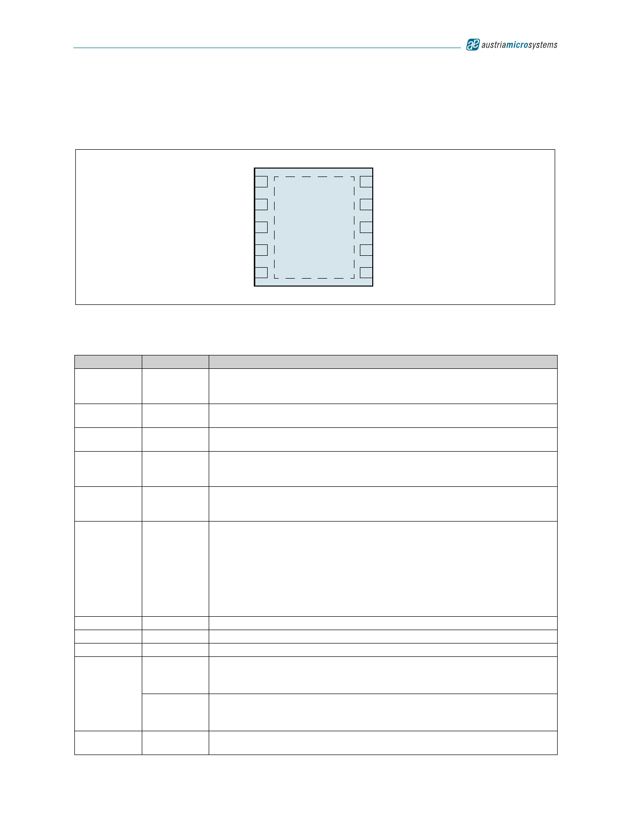
4 Pinout
Pin Assignments
Figure 2. Pin Assignments (Top View)
ISET 1
REF 2
GND 3
FB 4
OUT 5
10 ONN/ON
AS1326A/
AS1326B
9 POUT
8 LX
7 PGND
11 6 CLK/SEL
Pin Descriptions
Table 2. Pin Descriptions
Pin Number Pin Name
1
ISET
2
REF
3
GND
4
FB
5
OUT
6
CLK/SEL
7
PGND
8
LX
9
POUT
ONN
10
ON
11
NC
Description
N-Channel Current-Limit Control. For maximum current limit, connect to pin REF.
To reduce current, supply a voltage between pin REF and GND using a resistive
voltage-divider. If soft-start is desired, connect a capacitor from this pin to GND.
1.250V Internal Reference Bypass. Connect a 10nF ceramic bypass capacitor to
GND. Up to 50µA of external load current is allowed.
Ground. Connect this pin to PGND using a short trace. The exposed pad can be
used for this routing.
DC-DC Converter Feedback Input. To set fixed output voltage of +3.3V, connect
this pin to GND. For adjustable output of 2.5 to 5.0V, connect to a resistor-divider
network from pin OUT to GND. The set point for this pin is 1.24V.
IC Power, Supplied from the Output. Bypass this pin to GND with a 330nF
ceramic capacitor, and connect to POUT with a 10Ω series resistor (see Figure 19
on page 11).
Clock Input for the DC-DC Converter. This pin is also used to program the
operational mode as follows:
0 = Normal operation – the AS1326A operates at a fixed frequency, and switches
into automatic powersave operation if the load is minimized.
1 = Forced-PWM mode – the AS1326A operates in low-noise, constant-frequency
mode at all loads.
Clocked = Forced-PWM mode with the internal oscillator synchronized to this pin in
500 to 1200kHz range.
N-Channel Power MOSFET Switch Source
Inductor Connection
Power Output. P-channel synchronous rectifier source.
Enable Low (AS1326A only). Must be connected to GND for normal operation.
0 = The AS1326A is on.
1 = The AS1326A is off.
Enable High (AS1326B only). Must be connected to OUT for normal operation.
0 = The AS1326B is off.
1 = The AS1326B is on.
Exposed Pad. This pad is not connected internally. It can be used for ground
connection between GND and PGND.
www.austriamicrosystems.com
Revision 1.05
2 - 18
Share Link: 