AS1325 データシートの表示(PDF) - austriamicrosystems AG
部品番号
コンポーネント説明
一致するリスト
AS1325 Datasheet PDF : 17 Pages
| |||
AS1325
Data Sheet - Detailed Description
Shutdown
When pin SHDNN is low the AS1325 is switched off and no current is drawn from battery; when pin SHDNN is high the
device is switched on. If SHDNN is driven from a logic-level output, the logic high-level (on) should be referenced to
VOUT to avoid intermittently switching the device on.
Note: If pin SHDNN is not used, it should be connected directly to pin OUT.
In shutdown the battery input is connected to the output through the inductor and the internal synchronous rectifier P-
FET. This allows the input battery to provide backup power for devices such as an idle microcontroller, memory, or real-
time-clock, without the usual diode forward drop. In this way a separate backup battery is not needed.
In cases where there is residual voltage during shutdown, some small amount of energy will be transferred from pin
OUT to pin BATT immediately after shutdown, resulting in a momentary spike of the voltage at pin BATT. The ratio of
CIN and COUT partly determine the size and duration of this spike, as does the current-sink ability of the input device.
Low-Battery Cutoff
The AS1325 SHDNN trip threshold (1.228V) can be used as an input voltage detector that disables the device when
the battery input voltage falls to a pre-set level. An external resistor-divider network can be used to set the battery-
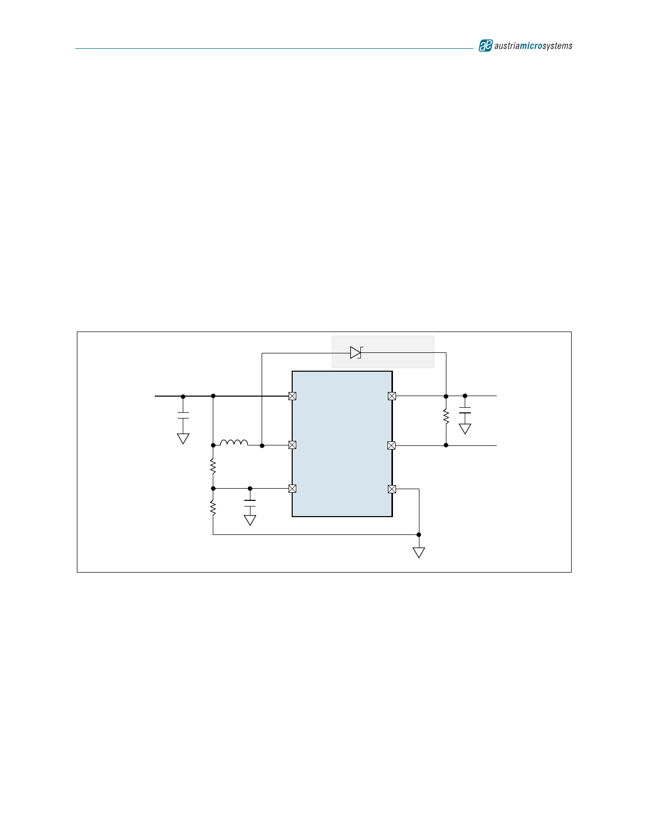
detection voltage (see Figure 28).
Figure 28. Low-Battery Cutoff Application Diagram
+1.5 to +3.3V or
+1.5 to +5.0V
Battery
CIN
22µF
R1
220kΩ
R2
1MΩ
L1
10µH
10nF
2
BATT
4
LX
1
SHDNN
+5.0V Output only
AS1325
5
OUT
R3
100kΩ
6
RESETN
3
GND
COUT
22µF
+3.3V or +5.0V
Output
Power-On
Reset
For the resistor-divider network shown in Figure 28, calculate the value for R1 by:
R1 = R2 x ((VOFF/VSHDNN) - 1)
Where:
VOFF is the battery voltage at which the AS1325 shuts down.
VSHDNN = 1.228V
The value of R2 should be between 100kΩ and 1MΩ to minimize battery drain.
(EQ 1)
Note: Input ripple can cause false shutdowns, therefore to minimize the effect of ripple, a low-value capacitor from
SHDNN to GND should be used to filter out input noise. The value of the capacitor should be such that the R/C
time constant is > 2ms.
www.austriamicrosystems.com
Revision 1.01
11 - 17
Share Link: 