AIC1722 データシートの表示(PDF) - Analog Intergrations
部品番号
コンポーネント説明
一致するリスト
AIC1722 Datasheet PDF : 6 Pages
| |||
AIC1722
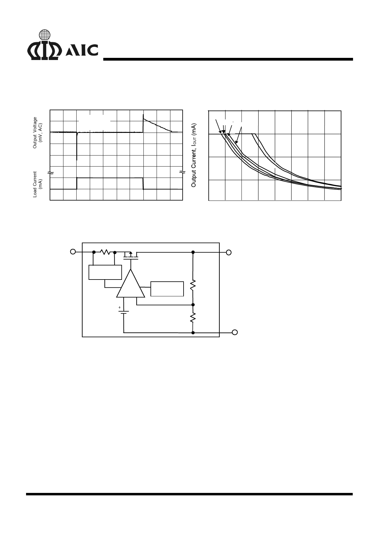
TYPICAL PERFORMANCE CHARACTERISTICS (Continued)
Load Transient Response
100
COUT= 1µF
VOUT= 5.2V
0
-100
-200
150
0.1
0
0.5 1.0
1.5
2.0 2.5 3.0
3.5
4.0 4.5 5.0
Time (mS)
Recommended Max. Output Current v.s. Input Voltage
400
3.3V
3.7V
3.5V
3.8V
300
200
5.2V
5V
100
0
4
5
6
7
8
9
10
11
12
Input Voltage VIN (V)
BLOCK DIAGRAM
VIN
CURRENT
LIMITING
-
ERROR
AMP
+
THERMAL
SHUTDOW N
1.235V
- Reference
VOUT
GND
PIN DESCRIPTION
VOUT PIN - Output pin.
GND PIN - Power GND.
VIN PIN - Power Supply Input.
APPLICATION INFORMATIONS
A 1µF (or greater) capacitor is required between
the AIC1722 output and ground for stability.
Without this capacitor the part will oscillate. Even
though most types of capacitor may work, the
equivalent series resistance (ESR) should be held
to 5Ω or less if Aluminum electrolytic type is used.
Many Aluminum electrolytics have electrolytes
that freeze at about -30°C, so solid tantalums are
recommended for operation below -25°C. The
value of this capacitor may be increased without
limit.
A 0.1µF capacitor (or greater) should be placed
from the AIC1722 input to ground if the lead
inductance between the input and power source
exceeds 500nH (approximately 10 inches of trace).
5
Share Link: 