AIC1648 データシートの表示(PDF) - Analog Intergrations
部品番号
コンポーネント説明
一致するリスト
AIC1648 Datasheet PDF : 10 Pages
| |||
AIC1648
Dimming Control
There are three different ways of dimming control
circuits as follows:
1. Using a PWM signal
PWM brightness control provides the widest
dimming range by pulsing the LEDs on and off at
full and zero current, respectively. The change of
average LED current depends on the duty cycle of
the PWM signal. Typically, a 0.1kHz to 1kHz
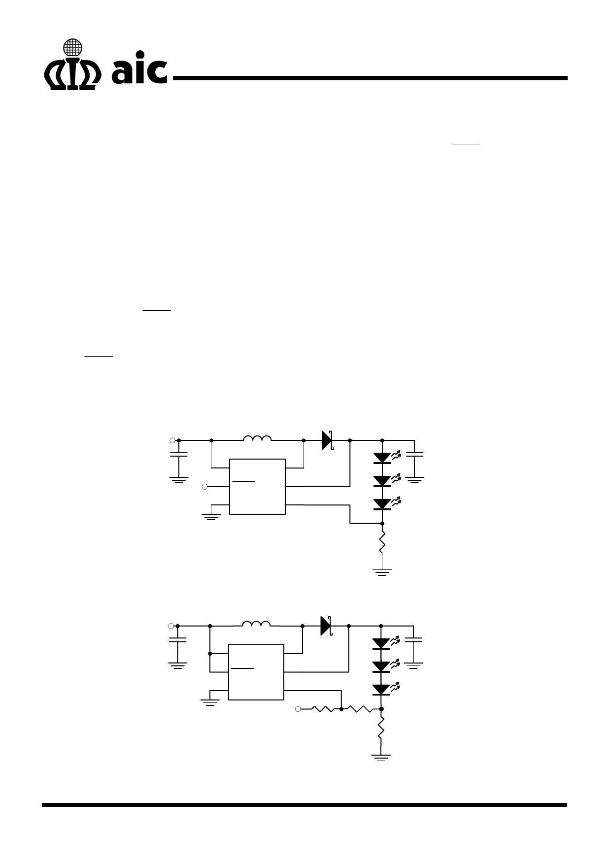
PWM signal is used. Two applications of PWM
dimming with AIC1648 are shown in Figure 16
and Figure 17. One, as Figure 16, uses PWM
signal to drive SHDN pin directly for dimming
control. The other, as Figure 17, employs PWM
signal going through a resistor to drive FB pin. If
the SHDN pin is used, the increase of duty cycle
results in LED brightness enhancement. If the FB
pin is used, on the contrary, the increase of duty
cycle will decrease its brightness. In this
application, LEDs are dimmed by FB pin and
turned off completely by SHDN .
2. Using a DC Voltage
For some applications, the preferred method of a
dimming control uses a variable DC voltage to
adjust LED current. The dimming control using a
DC voltage is shown in Figure 18. With a VDC
ranging from 0V to 5V, the selection of resistors in
Figure 18 results in dimming control of LED
current from 20mA to 0mA, respectively.
3. Using a Filtered PWM Signal
Filtered PWM signal can be considered as an
adjustable DC voltage. It can be used to replace
the variable DC voltage source in dimming
control. The circuit is shown in Figure 19.
VIN
C1
1µF
PWM
L
10µH
VIN SW
SHDN OVP
GND FB
AIC1648
D1
RB521S-30
C2
1µF
RFB
4.7Ω
Fig. 16 Dimming Control with a PWM Signal
VIN
C1
1µF
L
D1
10µH
VIN SW
RB521S-30
C2
1µF
SHDN OVP
GND FB
R2
AIC1648
PWM 51K
R1
1K
RFB
4.7Ω
Fig. 17 Dimming Control Using a PWM Signal
8
Share Link: 