ACT4072SH-T データシートの表示(PDF) - Active-Semi, Inc
部品番号
コンポーネント説明
一致するリスト
ACT4072SH-T Datasheet PDF : 10 Pages
| |||
Active-Semi
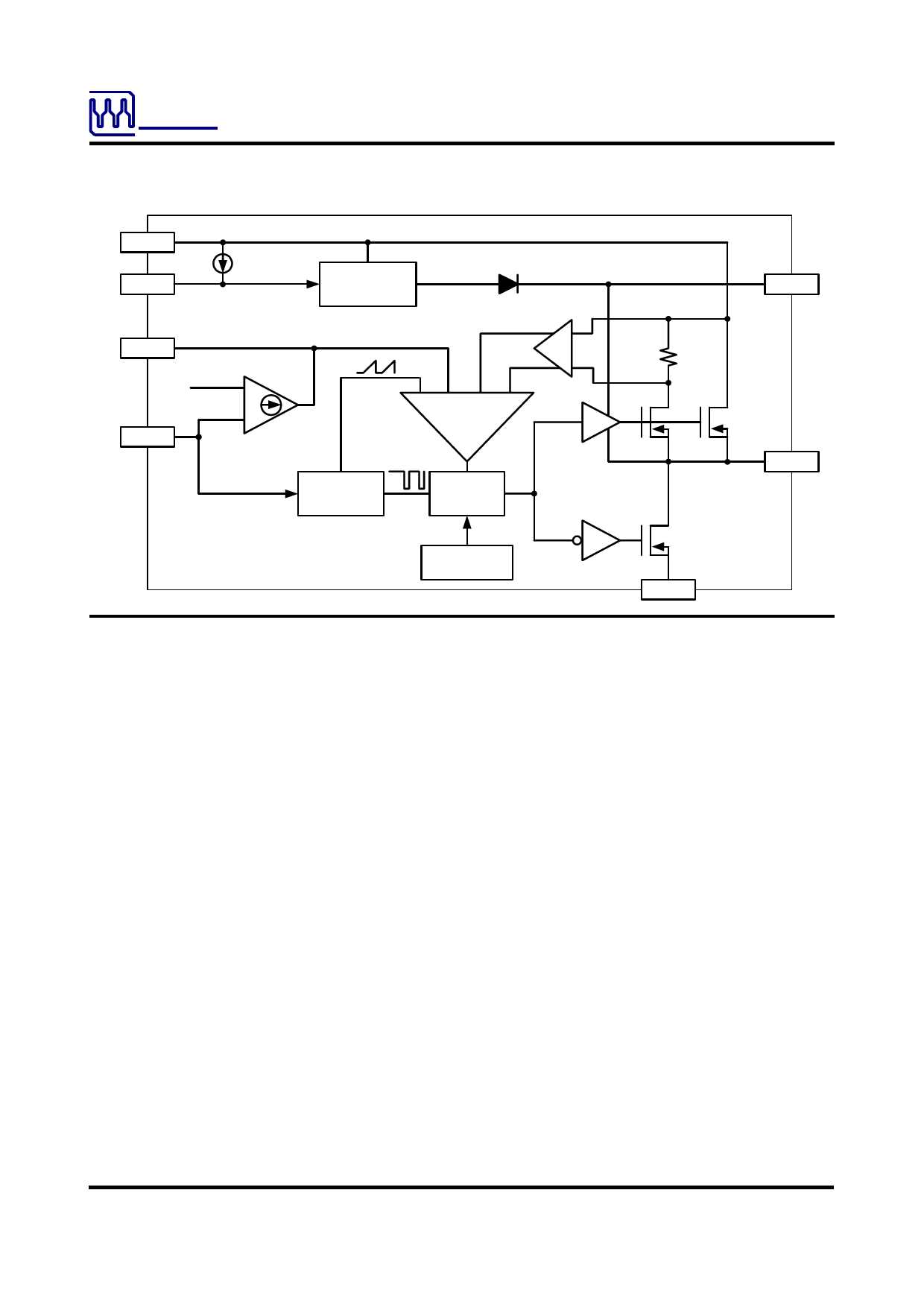
FUNCTIONAL BLOCK DIAGRAM
ACT4072
Rev2, 27-May-08
IN
EN
COMP
1.222V
FB
2µA
ENABLE
ERROR
AMPLIFIER
+
-
REGULATOR
&
REFERENCE
CURRENT SENSE
AMPLIFIER
+
-
+- +-
PWM
COMP
FOLDBACK
CONTROL
OSCILLATOR
&
RAMP
LOGIC
THERMAL
SHUTDOWN
BS
0.13OΩ
HIGH-SIDE
POWER
SWITCH
SW
10OΩ LOW-SIDE
POWER SWITCH
G
FUNCTIONAL DESCRIPTION
As seen in the Functional Block Diagram, the
ACT4072 is a current mode pulse width modulation
(PWM) converter. The converter operates as fol-
lows:
A switching cycle starts when the rising edge of the
Oscillator clock output causes the High-Side Power
Switch to turn on and the Low-Side Power Switch to
turn off. With the SW side of the inductor now con-
nected to IN, the inductor current ramps up to store
energy in its magnetic field. The inductor current
level is measured by the Current Sense Amplifier
and added to the Oscillator ramp signal. If the result-
ing summation is higher than the COMP voltage, the
output of the PWM Comparator goes high. When
this happens or when Oscillator clock output goes
low, the High-Side Power Switch turns off and the
Low-Side Power Switch turns on. At this point, the
SW side of the inductor swings to a diode voltage
below ground, causing the inductor current to de-
crease and magnetic energy to be transferred to the
output. This state continues until the cycle starts
again.
The High-Side Power Switch is driven by logic using
the BS bootstrap pin as the positive rail. This pin is
charged to VSW + 6V when the Low-Side Power
Switch turns on.
The COMP voltage is the integration of the error
between the FB input and the internal 1.222V refer-
ence. If FB is lower than the reference voltage,
COMP tends to go higher to increase current to the
output. Current limit happens when COMP reaches
its maximum clamp value of 2.55V.
The Oscillator normally switches at 420kHz. How-
ever, if the FB voltage is less than 0.7V, then the
switching frequency decreases until it reaches a
minimum of 60kHz at VFB = 0.5V.
Shutdown Control
The ACT4072 has an enable input EN for turning
the IC on or off. When EN is less than 0.7V, the IC
is in 6µA low current shutdown mode and the out-
put is discharged through the Low-Side Power
Switch. When EN is higher than 1.3V, the IC is in
normal operation mode. EN is internally pulled up
with a 2µA current source and can be left uncon-
nected for always-on operation.
Thermal Shutdown
The ACT4072 automatically turns off when its junc-
tion temperature exceeds 160°C.
Innovative PowerTM
-4-
www.active-semi.com
Copyright © 2008 Active-Semi, Inc.
Share Link: 