A700D127M006ATE018 データシートの表示(PDF) - KEMET
部品番号
コンポーネント説明
一致するリスト
A700D127M006ATE018 Datasheet PDF : 12 Pages
| |||
ALUMINUM ORGANIC CAPACITORS
Performance Characteristics
RL - Capacitor Leakage Resistance. Typically it can
be 35 K to 2.5 MOhms depending on voltage -
capacitance. It can exceed 1012 ohms in monolithic
ceramics and in film capacitors.
Rd - The dielectric loss contributed by dielectric
absorption and molecular polarization. It becomes
very significant in high frequency measurements and
applications. Its value varies with frequency.
Cd - The inherent dielectric absorption of the solid
aluminum capacitor.
As frequency increases, Xc continues to decrease
according to its equation. There is unavoidable
inductance as well as resistance in all capacitors,
and at some point in frequency, the reactance ceas-
es to be capacitive and becomes inductive. This fre-
quency is call the self-resonant point.
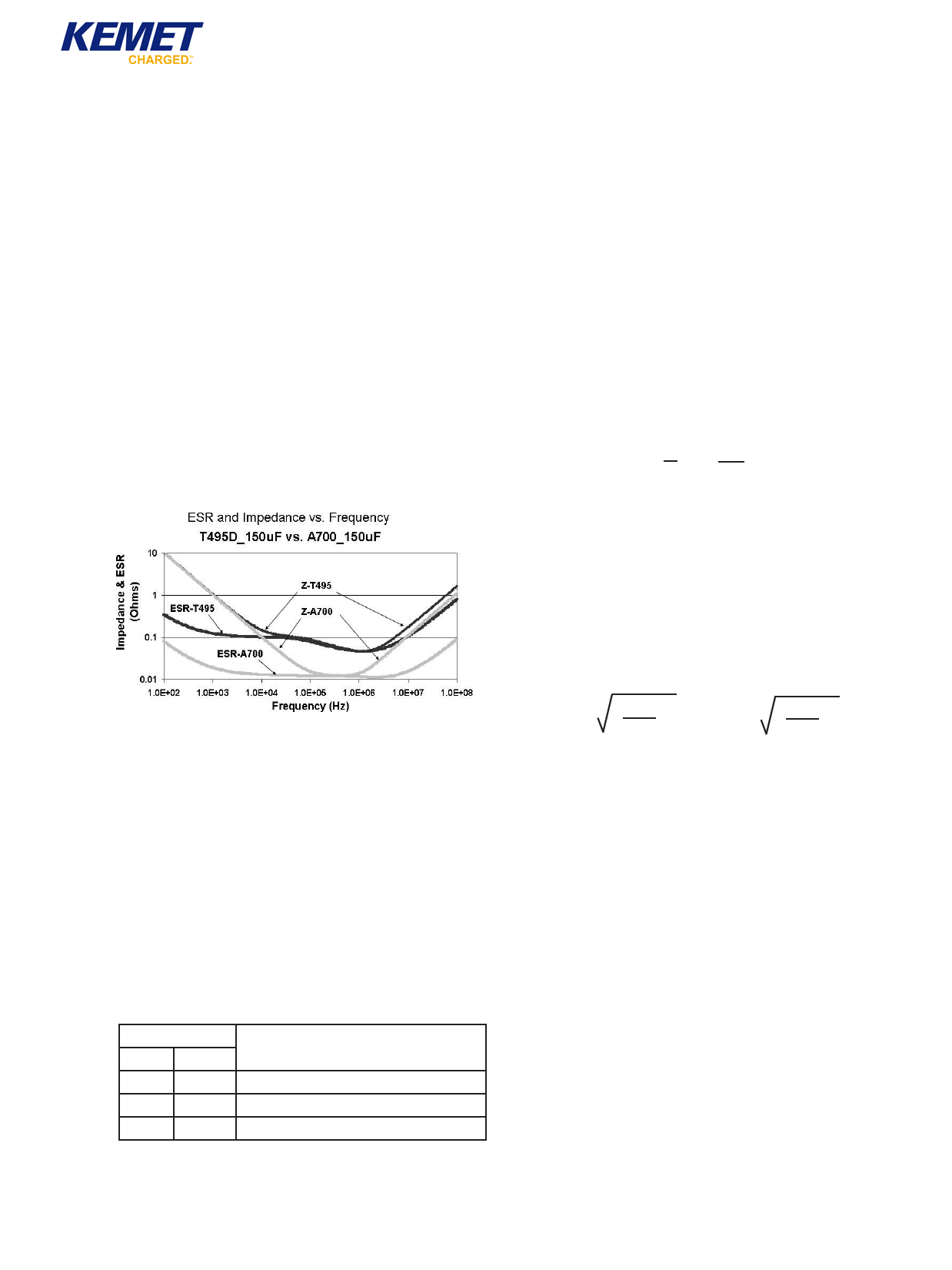
Figure 4 compares the frequency response of an
AO-CAP to a Tantalum chip. Maximum limits for 100
kHz ESR are listed in the part number tables for
each series.
10. Ripple Current/Voltage
Permissible AC ripple voltage and current are related
to equivalent series resistance (ESR) and power dis-
sipation capability.
Permissible ripple current which may be applied
is limited by two criteria:
a. The resulting voltage across the capacitor with the
summation of DC bias and peak voltage of the
AC portion must not exceed the rated voltage of
the capacitor.
b. The negative peak AC voltage, in combination
with bias voltage, if any, must not exceed the per-
missible reverse voltage ratings presented in
Section 5.
Actual power dissipated may be calculated from the
following:
P = I2R
Substituting I = E ; P = E2R
Z
Z2
Where:
I = rms ripple current (Amperes)
E = rms ripple voltage (Volts)
P = power (Watts)
Z = impedance at specified frequency (ohms)
R = ESR(Ohms)
Using P max from Table 3, maximum allowable rms
ripple current or voltage may be determined as fol-
lows:
Figure 4.
9. AC Power Dissipation
Power dissipation is a function of capacitor size and
materials. Maximum power ratings have been estab-
lished for all case sizes to prevent overheating. In
actual use, the capacitor's ability to dissipate the
heat generated at any given power level may be
affected by a variety of circuit factors. These include
board density, pad size, heat sinks and air circulation.
Power capability is determined based on a 20°C tem-
perature rise. A higher temperature rise and therefore
higher power capability is allowable as long as the
ambient temperature plus temperature rise due to rip-
ple current does not exceed the rated temperature of
the part.
Case Code Maximum Power Dissipation mWatts
KEMET EIA @ +25°C with 20° Temperature Rise
V 7343-20
270
D 7343-31
250
X 7343-43
225
Imax =
Pmax
ESR
Emax = Z
Pmax
R
Where:
Imax = Maximum rupple current (ARMS)
Pmax = Maximum Power @ allowable ∆T normally
+20°C
Emax = Maximum ripple voltage (VRMS)
Refer to part number listings for permittable Arms
limits.
Table 3 - AO Capacitor Power Dissipation Ratings
60
©KEMET Electronics Corporation, P.O. Box 5928, Greenville, S.C. 29606, (864) 963-6300
Share Link: 