IMIFS741 データシートの表示(PDF) - Unspecified
部品番号
コンポーネント説明
一致するリスト
IMIFS741 Datasheet PDF : 16 Pages
| |||
Approved Product
FS741
Low EMI Spectrum Spread Clock
THEORY OF OPERATION
The FS741 is a Phase Lock Loop (PLL) type clock generator using Direct Digital Synthesis (DDS). By precisely
controlling the bandwidth of the output clock, the FS741 becomes a Low EMI clock generator. The theory and
detailed operation of the FS741 will be discussed in the following sections.
EMI
All clocks generate unwanted energy in their harmonics. Conventional digital clocks are square waves with a duty
cycle that is very close to 50 %. Because of the 50/50 duty cycle, digital clocks generate most of their harmonic
energy in the odd harmonics, i.e.; 3rd, 5th, 7th etc. It is possible to reduce the amount of energy contained in the
fundamental and harmonics by increasing the bandwidth of the fundamental clock frequency. Conventional digital
clocks have a very high Q factor, which means that all of the energy at that frequency is concentrated in a very
narrow bandwidth, consequently, higher energy peaks. Regulatory agencies test electronic equipment by the
amount of peak energy radiated from the equipment. By reducing the peak energy at the fundamental and
harmonics, the equipment under test is able to satisfy agency requirements for Electro-Magnetic Interference
(EMI). Conventional methods of reducing EMI have been to use shielding, filtering, multi-layer PCB’s etc. The
FS741 uses the approach of reducing the peak energy in the clock by increasing the clock bandwidth, and
lowering the Q.
SSCG
The FS741 uses a proprietary technique to modulate the clock over a very narrow bandwidth and controlled rate of
change, both peak and cycle to cycle. The FS741 takes a narrow band digital reference clock in the range 4 - 68
MHz and produces a clock that sweeps between a controlled start and stop frequency and precise rate of change.
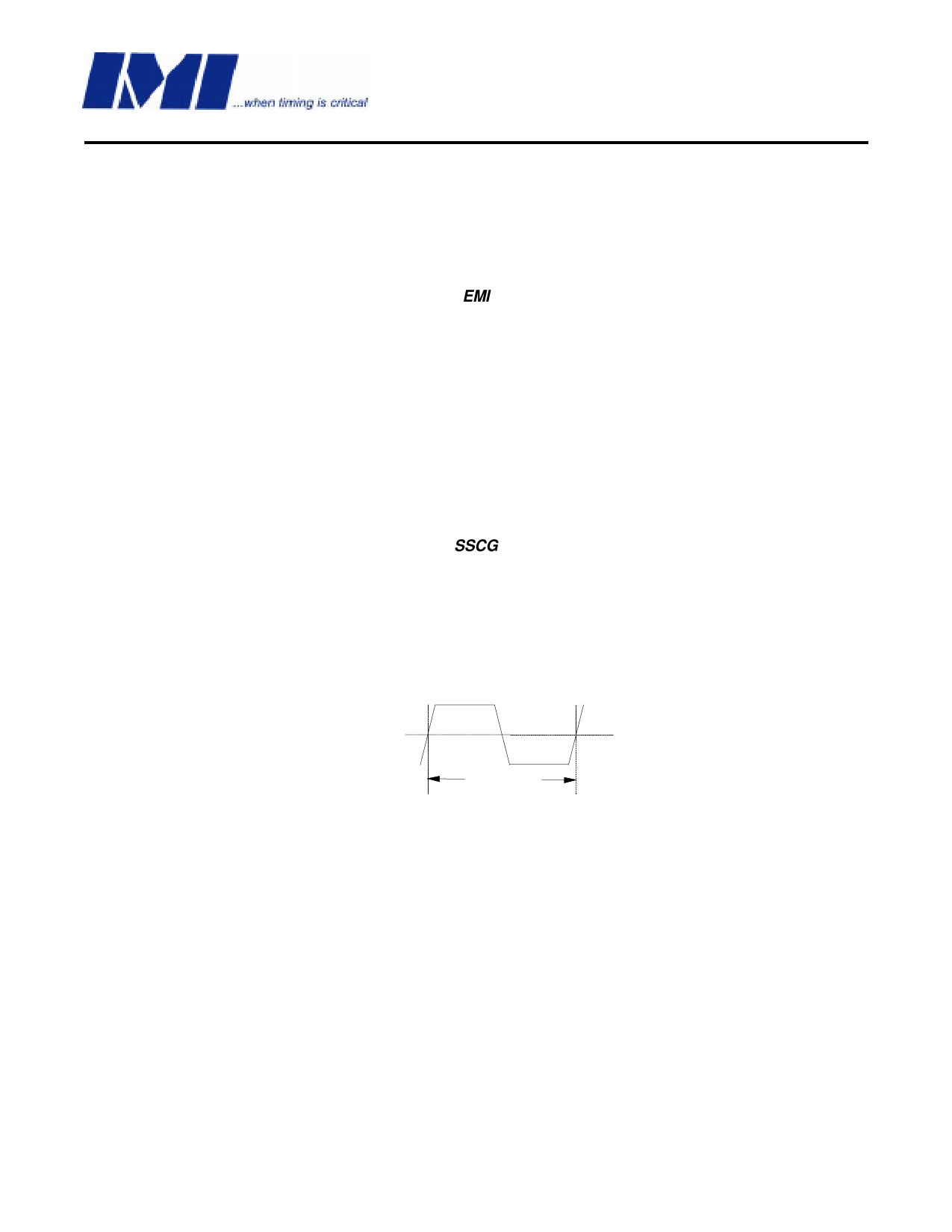
To understand what happens to an SSCG clock, consider that we have a 20 MHz clock with a 50 % duty cycle.
From a 20 MHz clock we know the following;
Clock Frequency = Fc = 20 MHz.
Clock Period = Tc = 1/20 MHz = 50 ns
50%
50%
Figure 6.
Tc = 50 ns.
20 MHz Unmodulated Clock
Consider that this 20 MHz clock is applied to the Xin input of the FS741, either as an externally driven clock or as
the result of a parallel resonant crystal connected to pins 1 and 2 of the FS741. Also consider that the FS741 is
operating from a 5 volt DC power supply and the loop filter is set for a total bandwidth spread of 2%. Refer to table
6 on page 7.
From the above parameters, the output clock at Modout will be sweeping symetrically around a center frequency
of 20 MHz.
The minimum and maximum extremes of this clock will be +200 Khz and -200 KHz.. So, we have a clock that is
sweeping from 19.8 MHz to 20.2 MHz and back again. If we were to look at this clock on a spectrum analyzer we
would see the picture in Figure 7. Keep in mind that this is a drawing of a perfect clock with no noise.
International Microcircuits, Inc.
525 Los Coches St., Milpitas, 95035 408-263-6300, FAX 408-263-6571
http:/www.imicorp.com
4/5/1999
Rev. 2.1
Page 10 of 16
Share Link: 