MAX3421E(2006) データシートの表示(PDF) - Maxim Integrated
部品番号
コンポーネント説明
一致するリスト
MAX3421E Datasheet PDF : 29 Pages
| |||
USB Peripheral/Host Controller
with SPI Interface
Features in Host Operation
♦ Eleven Registers (R21–R31) are Added to the
MAX3420E Register Set to Control Host Operation
♦ Host Controller Operates at Full Speed or Low
Speed
♦ FIFOS
SNDFIFO: Send FIFO, Double-Buffered 64-Byte
RCVFIFO: Receive FIFO, Double-Buffered 64-Byte
♦ Handles DATA0/DATA1 Toggle Generation and
Checking
♦ Performs Error Checking for All Transfers
♦ Automatically Generates SOF (Full-Speed)/EOP
(Low-Speed) at 1ms Intervals
♦ Automatically Synchronizes Host Transfers with
Beginning of Frame (SOF/EOP)
♦ Reports Results of Host Requests
♦ Supports USB Hubs
♦ Supports ISOCHRONOUS Transfers
♦ Simple Programming
SIE Automatically Generates Periodic SOF
(Full-Speed) or EOP (Low-Speed) Frame
Markers
SPI Master Loads Data, Sets Function Address,
Endpoint, and Transfer Type, and Initiates the
Transfer
MAX3421E Responds with an Interrupt and
Result Code Indicating Peripheral Response
Transfer Request Can be Loaded Any Time
SIE Synchronizes with Frame Markers
For Multipacket Transfers, the SIE
Automatically Maintains and Checks the
Data Toggles
Features in Peripheral Operation
♦ Built-In Endpoint FIFOS
EP0: CONTROL (64 bytes)
EP1: OUT, Bulk or Interrupt, 2 x 64 Bytes
(Double-Buffered)
EP2: IN, Bulk or Interrupt, 2 x 64 Bytes (Double-
Buffered)
EP3: IN, Bulk or Interrupt (64 Bytes)
♦ Double-Buffered Data Endpoints Increase
Throughput by Allowing the SPI Master to
Transfer Data Concurrent with USB Transfers
♦ SETUP Data Has its Own 8-Byte FIFO, Simplifying
Firmware
Typical Application Circuits
3.3V
REGULATOR
USB
MAX3421E
SPI
3, 4
µP
INT
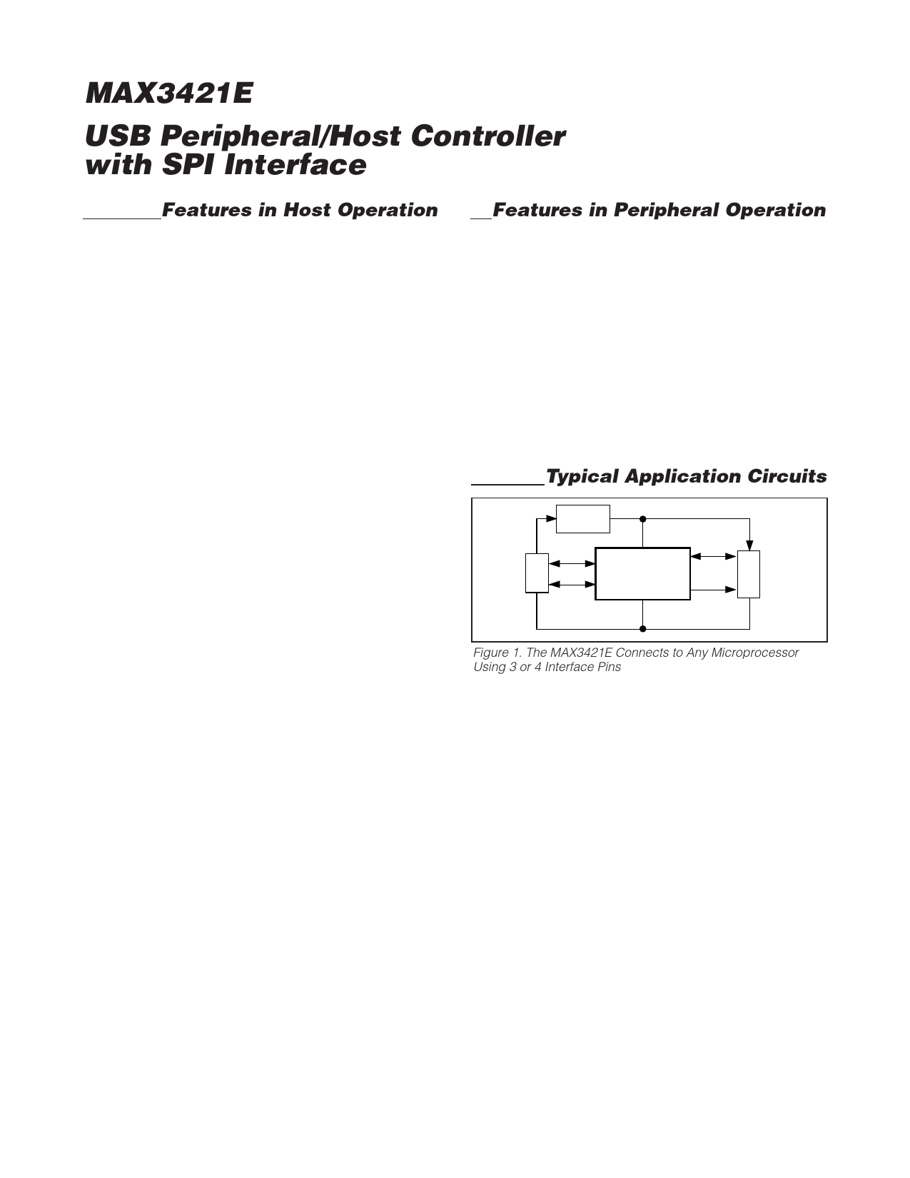
Figure 1. The MAX3421E Connects to Any Microprocessor
Using 3 or 4 Interface Pins
The MAX3421E connects to any microprocessor (µP)
using 3 or 4 interface pins (Figure 1). On a simple
microprocessor without SPI hardware, these can be
bit-banged general-purpose I/O pins. Eight GPIN and
eight GPOUT pins on the MAX3421E more than
replace the µP pins necessary to implement the inter-
face. Although the MAX3421E SPI hardware includes
separate data-in (MOSI, master-out, slave-in) and data-
out (MISO, master-in, slave-out) pins, the SPI interface
can also be configured for the MOSI pin to carry bidi-
rectional data, saving an interface pin. This is referred
to as half-duplex mode.
2 _______________________________________________________________________________________
Share Link: 