EM-1SRI データシートの表示(PDF) - Systemsensor advanced ideas.
部品番号
コンポーネント説明
一致するリスト
EM-1SRI Datasheet PDF : 4 Pages
| |||
Auto Addressing
Eclipse Series devices are capable of supporting auto ad-
dressing, if the fire alarm control panel is designed to do
so. In auto addressing, the control panel, through the use
of each device’s on-board isolators, can automatically as-
sign device addresses. In order to control which devices
are addressed first in wiring configurations with branches,
a branch marker can be set at a particular device. A branch
marker is an electronic value from 0 to 255 stored in the
device memory. The branch markers are set with the IR
configuration tool, EA-CT.
TESTING
The following resistance values can be used to test the
module after installation:
Short Circuit: <50Ω
Open Circuit: >1MΩ
Ground Fault: <50Ω
WARNING
All relay switch contacts are shipped in the standby state
(open) state, but may have transferred to the activated
(closed) state during shipping. To ensure that the switch
contacts are in their correct state, modules must be made
to communicate with the panel before connecting circuits
controlled by the module.
Terminal Definitions
T1 (+) SLC in/out
T2 (–) SLC in/out
T3 (+) SLC in/out
T4 (–) SLC in/out
T7 (–) external power line in/out
T8 (+) external power line in/out
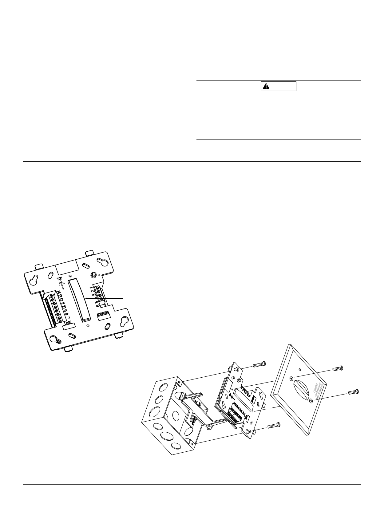
Figure 1A: Supervised Control Module
LED
INDICATOR
IR
RECEIVER
T9 (–) external power line in/out
T10 (+) external power line in/out
T11 NAC (+) A/B
T12 NAC (–) A/B
T13 NAC (–) Class A
T14 NAC (+) Class A
C0164-00
Figure 1B: Module mounting with barrier (model no. EA-CB)
D500-54-00
C0183-00
2
I56-2016-004
Share Link: 