TC74ACT08P(2012) データシートの表示(PDF) - Toshiba
部品番号
コンポーネント説明
一致するリスト
TC74ACT08P Datasheet PDF : 7 Pages
| |||
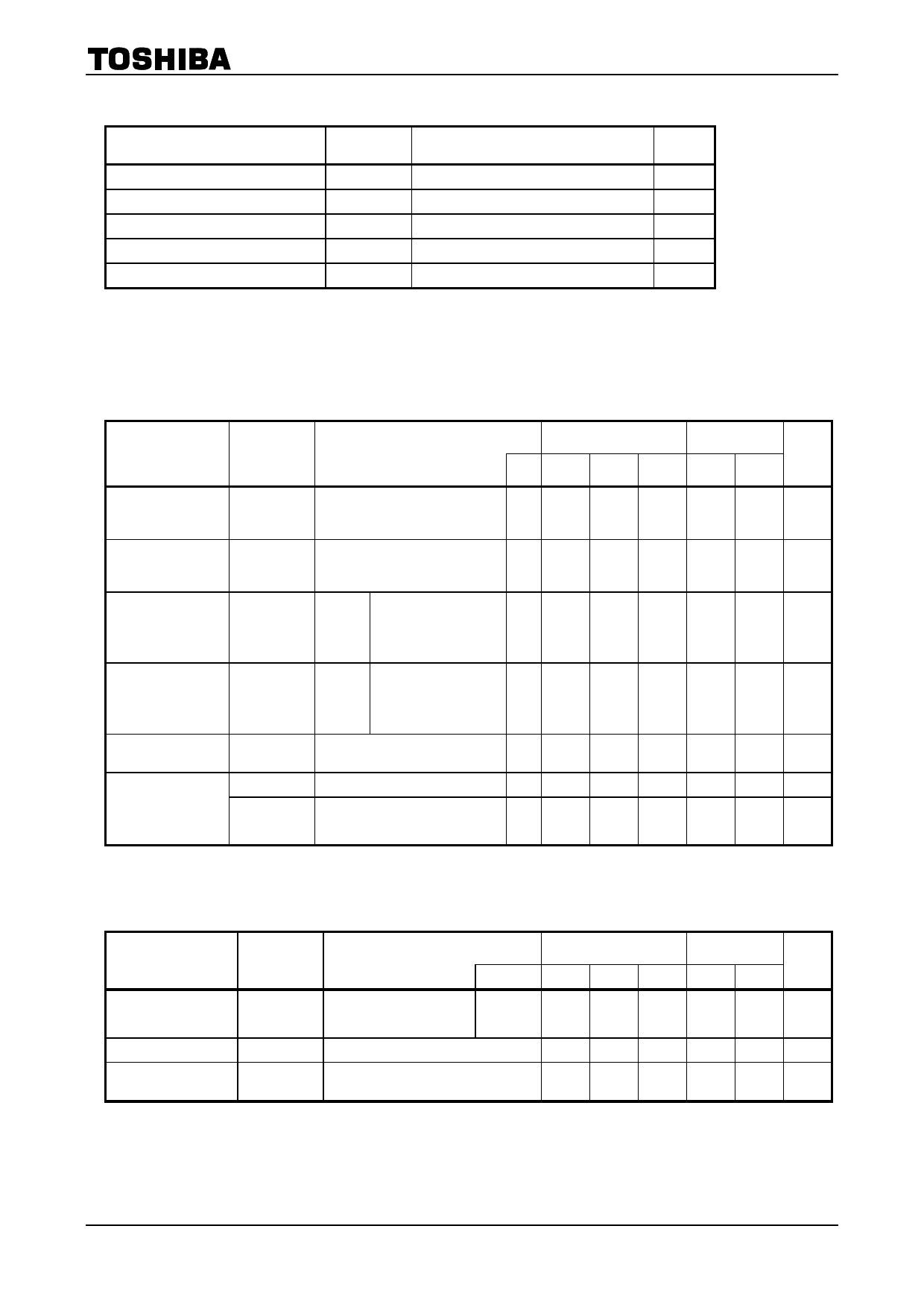
Operating Ranges (Note)
TC74ACT08P/F/FT
Characteristics
Symbol
Rating
Unit
Supply voltage
Input voltage
Output voltage
Operating temperature
Input rise and fall time
VCC
VIN
VOUT
Topr
dt/dV
4.5 to 5.5
0 to VCC
0 to VCC
−40 to 85
0 to 10
V
V
V
°C
ns/V
Note: The operating ranges must be maintained to ensure the normal operation of the device.
Unused inputs must be tied to either VCC or GND.
Electrical Characteristics
DC Characteristics
Characteristics
Symbol
High-level input
voltage
VIH
Test Condition
―
Ta = 25°C
Ta =
−40 to 85°C
Unit
VCC
(V)
Min
Typ.
Max
Min
Max
4.5
to 2.0
―
―
2.0
―
V
5.5
Low-level input
voltage
VIL
4.5
―
to ―
―
0.8
―
0.8
V
5.5
High-level output
voltage
Low-level output
voltage
Input leakage
current
VOH
VOL
IIN
IOH = −50 μA
4.5 4.4 4.5
―
4.4
―
VIN
= VIH
IOH = −24 mA
4.5 3.94 ―
― 3.80 ―
V
IOH = −75 mA (Note) 5.5 ―
―
― 3.85 ―
VIN
IOL = 50 μA
4.5 ―
0.0 0.1
―
0.1
= VIH or IOL = 24 mA
4.5 ―
―
0.36 ―
0.44
V
VIL
IOL = 75 mA (Note) 5.5 ―
―
―
― 1.65
VIN = VCC or GND
5.5 ―
― ±0.1 ― ±1.0 μA
Quiescent supply
current
ICC
VIN = VCC or GND
Per input: VIN = 3.4 V
IC
Other input: VCC or GND
5.5 ―
5.5 ―
―
4.0
― 40.0 μA
― 1.35 ―
1.5 mA
Note: This spec indicates the capability of driving 50 Ω transmission lines.
One output should be tested at a time for a 10 ms maximum duration.
AC Characteristics (CL = 50 pF, RL = 500 Ω, input: tr = tf = 3 ns)
Characteristics
Symbol
Test Condition
Ta = 25°C
Ta =
−40 to 85°C Unit
VCC (V) Min Typ. Max Min Max
Propagation delay
tpLH
time
tpHL
―
5.0 ± 0.5 ―
5.4 8.7 1.0 10.0 ns
Input capacitance
CIN
―
―
5
10
―
10
pF
Power dissipation
capacitance
CPD
(Note) ―
21
―
―
―
pF
Note:
CPD is defined as the value of the internal equivalent capacitance which is calculated from the operating
current consumption without load.
Average operating current can be obtained by the equation:
ICC (opr) = CPD·VCC·fIN + ICC/4 (per gate)
3
2012-02-29
Share Link: 