ACP104E データシートの表示(PDF) - MicroPower Direct, LLC
部品番号
コンポーネント説明
一致するリスト
ACP104E Datasheet PDF : 2 Pages
| |||
Model Selection Guide
www.micropowerdirect.com
Model
Number
ACP101E
ACP102E
ACP103E
ACP104E
ACP111E
ACP112E
ACP113E
ACP114E
Input
Voltage (VDC)
Current (mA)
Nominal Range Full-Load No-Load
5
4.5 - 5.5
270
50
5
4.5 - 5.5
256
50
5
4.5 - 5.5
260
50
5
4.5 - 5.5
263
50
12 10.8 - 13.2 114
20
12 10.8 - 13.2 127
20
12 10.8 - 13.2 110
20
12 10.8 - 13.2 111
20
Voltage
(VDC)
5.0
9.0
12.0
15.0
5.0
9.0
12.0
15.0
Output
Current
(mA, Max)
200.0
111.0
83.0
67.0
200.0
111.0
83.0
67.0
Current
(mA, Min)
20.0
12.0
9.0
7.0
20.0
12.0
9.0
7.0
Load Regulation
(% Typ)
12.8
8.3
6.8
6.3
12.8
8.3
6.8
6.3
(% Max)
15.0
15.0
15.0
15.0
15.0
15.0
15.0
15.0
Efficiency
(%, Typ)
74
78
77
76
73
74
76
75
Fuse Rating
Slow-Blow
(mA)
500
500
500
500
200
200
200
200
Notes:
1. Output load regulation is specified for a load change of 10% to 100%.
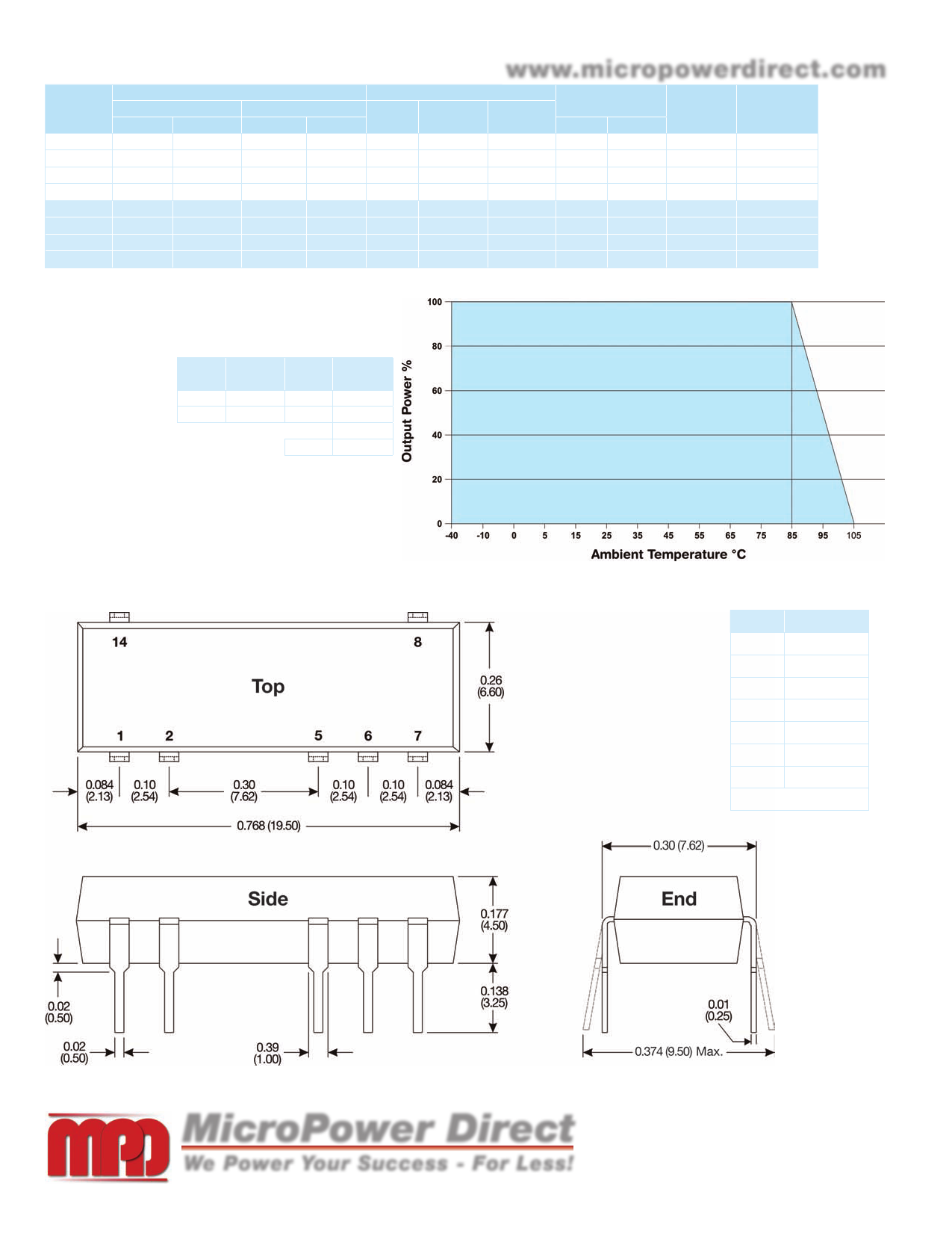
Derating Curve
2. These units should not be operated with a load under 10% of full load. Operation
at no-load may cause damage to the unit.
3. These converters will operate without external components. However, when measur-
ing output ripple, it is recommended that an external ceramic capacitor be placed
from the +Vout pin to the
-Vout pin. An input capacitor
will enhance stability over
Vin
Input
Capacitor
Vout
Output
Capacitor
temperature and input line
variations. Recommended
5 VDC
capacitor values are given 12 VDC
4.7 µF 5 VDC 10.0 µF
2.2 µF 9 VDC 4.7 µF
in the table at right. For
12 VDC 2.2 µF
applications requiring very
low output noise levels, a
15 VDC 1.0 µF
simple LC filter should be effective.
4. Given for frequency range of 5 to 500 Hz and PSD of 0.0248 g2/Hz.
Tested on X, Y & Z axis for 60 minutes.
5. It is recommended that a fuse be used on the input of a power supply for protection.
See the Model Selection table above for the correct rating.
Mechanical Dimensions
Pin Connections
Pin Description
1
+Vin
2
-Vin
5
-Vout
6
+Vout
7
NC
8
NC
14
NC
NC = No Connection
MicroPower Direct
Notes:
• All dimensions are typical in inches (mm)
• Tolerance x.xx = ±0.01 (±0.25)
• Pin 1 is marked by a “dot” or indentation on the top of the unit
We Power Your Success - For Less!
292 Page Street Ste D Stoughton, MA 02072 • TEL: (781) 344-8226 • FAX: (781) 344-8481 • E-Mail: sales@micropowerdirect.com
Share Link: 