MP1423 データシートの表示(PDF) - Monolithic Power Systems
部品番号
コンポーネント説明
一致するリスト
MP1423 Datasheet PDF : 11 Pages
| |||
TM
MP1423 – 3A, 23V, 385KHz STEP-DOWN CONVERTER
Compensation Components
MP1423 employs current mode control for easy
compensation and fast transient response. The
system stability and transient response are
controlled through the COMP pin. COMP pin is
the output of the internal transconductance
error amplifier. A series capacitor-resistor
combination sets a pole-zero combination to
control the characteristics of the control system.
The DC gain of the voltage feedback loop is
given by:
A VDC
= RLOAD
× GCS
× A VEA
×
VFB
VOUT
Where AVEA is the error amplifier voltage gain,
400V/V; GCS is the current sense
transconductance, 3.8A/V; RLOAD is the load
resistor value.
The system has two poles of importance. One
is due to the compensation capacitor (C3) and
the output resistor of error amplifier, and the
other is due to the output capacitor and the load
resistor. These poles are located at:
fP1
=
GEA
2π × C3 × A VEA
fP2
=
1
2π × C2 × RLOAD
Where GEA is the error amplifier
transconductance, 800µA/V.
The system has one zero of importance, due to
the compensation capacitor (C3) and the
compensation resistor (R3). This zero is located
at:
fZ1
=
1
2π × C3 × R3
The system may have another zero of
importance, if the output capacitor has a large
capacitance and/or a high ESR value. The zero,
due to the ESR and capacitance of the output
capacitor, is located at:
fESR
=
1
2π × C2 × RESR
In this case, a third pole set by the
compensation capacitor (C6) and the
compensation resistor (R3) is used to
compensate the effect of the ESR zero on the
loop gain. This pole is located at:
fP3
=
1
2π × C6 × R3
The goal of compensation design is to shape
the converter transfer function to get a desired
loop gain. The system crossover frequency
where the feedback loop has the unity gain is
important.
Lower crossover frequencies result in slower
line and load transient responses, while higher
crossover frequencies could cause system
unstable. A good rule of thumb is to set the
crossover frequency to approximately one-tenth
of the switching frequency. Switching frequency
for the MP1423 is 385KHz, so the desired
crossover frequency is around 38KHz.
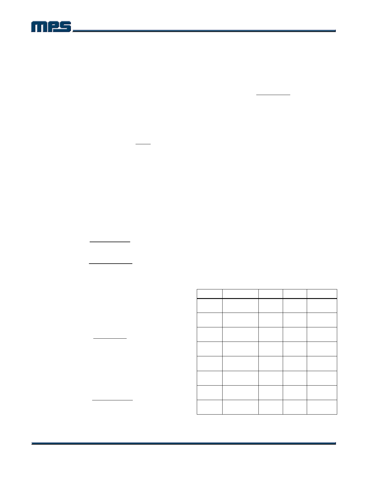
Table 3 lists the typical values of compensation
components for some standard output voltages
with various output capacitors and inductors.
The values of the compensation components
have been optimized for fast transient
responses and good stability at given
conditions.
Table 3—Compensation Values for Typical
Output Voltage/Capacitor Combinations
VOUT
2.5V
3.3V
5V
12V
2.5V
3.3V
5V
12V
C2
22µF
Ceramic
22µF
Ceramic
22µF
Ceramic
22µF
Ceramic
560µF Al.
30mΩ ESR
560µF Al
30mΩ ESR
470µF Al.
30mΩ ESR
220µF Al.
30mΩ ESR
R3
3.9kΩ
4.7kΩ
7.5kΩ
16.9kΩ
91kΩ
120kΩ
100kΩ
169kΩ
C3
5.6nF
4.7nF
4.7nF
1.5nF
1nF
1nF
1nF
1nF
C6
None
None
None
None
150pF
120pF
120pF
39pF
MP1423 Rev. 1.1
www.MonolithicPower.com
7
1/6/2006
MPS Proprietary Information. Unauthorized Photocopy and Duplication Prohibited.
© 2006 MPS. All Rights Reserved.
Share Link: 