PBL3852 データシートの表示(PDF) - Ericsson
部品番号
コンポーネント説明
一致するリスト
PBL3852 Datasheet PDF : 24 Pages
| |||
PBL 3852
Functional Description
Design procedure
+Line
1. Set the circuit impedance to the line,
either 600Ω or complex. (R19 and C9).
C9 should be big enough to give low
impedance compared with R19 in the
telephone speech frequency band.
Too large C9 will make the start-up
slow.
PBL 3852
1
a)
b)
c)
4
R19
2. Set the DC-characteristic that is
required in the PTT specification or in
case of a system telephone in the PBX
3
2
specification (R7). There are also
internal circuit dependent requirements
like supply voltages etc.
C10
R7
3. Set the attac point where the line length
regulation is supposed to cut in
(R14,R15 and R16). Note that in some
countries the line length regulation is
not allowed. In most cases the
end result is better and more readily
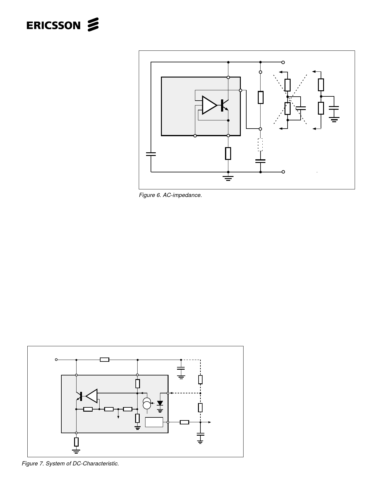
Figure 6. AC-impedance.
achieved by using the line length
regulation (line loss compensation)
Impedance to the line
than without.
The AC- impedance to the line is set by
4. Set the transmitter gain, regulation and C10, R19 and C9. Fig. 6. The circuits
frequency response. See text for the relatively high (≈ 20k with R7 = 75Ω)
dynamic limiting feature.
5. Set the receiver gain and frequency
response. See text how to limit the
max. swing to the earphone.
parallel impedance will influence it to
some extent. At low frequencies the
influence of the C9 can not be neglected.
Series resistance of the C9 that is
dependent on temperature and quality will
6. Adjust the side tone balancing network. cause that some of the line signal will
7. Set the RFI suppression components enter pin 4 and generate a closed loop in
in case necessary. In two piece
the transmitter amplifier that will create an
telephones the often ”helically” wound active impedance thus lowering the
cord acts as an aerial where especially impedance to the line. The impedance at
the microphone input with its high gain high frequencies is set by C10 that also
and input impedance is the more
acts as a RFI suppressor.
sensitive.
In many specifications the impedance
towards the line is specified as a complex
network. See fig. 6. In case a) the error
+Line
R19
1
PBL 3852
+
-
2
R7
Ref=1.16V
4
- I pin5
+
C9
5
I pin5
R20
R21
DC-
supply
9
DC1
R3
+
C2
Figure 7. System of DC-Characteristic.
Rs
≈1Ω
+
C9
Example:
The complex network
220Ω + 820Ω//115nF
-Line
signal entering pin 4 is set by the ratio
≈Rs/R19 (909Ω), where in case b) the
ratio at high frequency will be Rs/220Ω
because the 820Ω resistor is bypassed by
a capacitor. To help up this situation the
complex network capacitor is connected
directly to ground, case c) making the
ratio Rs/220Ω+820Ω and thus lessening
the error signal. Conclusion: Use case c)
when complex impedance is specified.
DC - characteristic
The DC - characteristic that a telephone
set has to fulfill is mainly given by the
network administrator.Following para-
meters are useful to know when the DC
behaviour of the telephone is to be set:
• The voltage of the feeding system
• The line feeding resistance 2 x.... ohms
• The maximum current from the line at
zero line length
• The min. current at which the telephone
has to work (basic function)
• The lowest and highest voltage
permissible across the telephone set.
• The highest voltage that the telephone
may have at different line currents is
normally set by the network owners
specification. The lowest voltage for the
telephone is normally set by the
different voltages that are needed for
the different parts of the telephone. For
ex. for transmitter output amplifier,
receiver output amplifier, dialler,
speech switching and loudspeaker
amplifier in a handsfree telephone etc.
5
Share Link: 