PI6C102-16BH データシートの表示(PDF) - Pericom Semiconductor
部品番号
コンポーネント説明
一致するリスト
PI6C102-16BH Datasheet PDF : 12 Pages
| |||
PI6C102-16
Spread Spectrum Clock Synthesizer
for Mobile Pentium II 1122334455667788990011223344556677889900112233445566778899001122112233445566778899001122334455667788990011223344556677889900112211223344556677889900112233445566778899001122334455667788990011221122334455667788990011223344556677889900112233445566778899001122112233445566778899001122
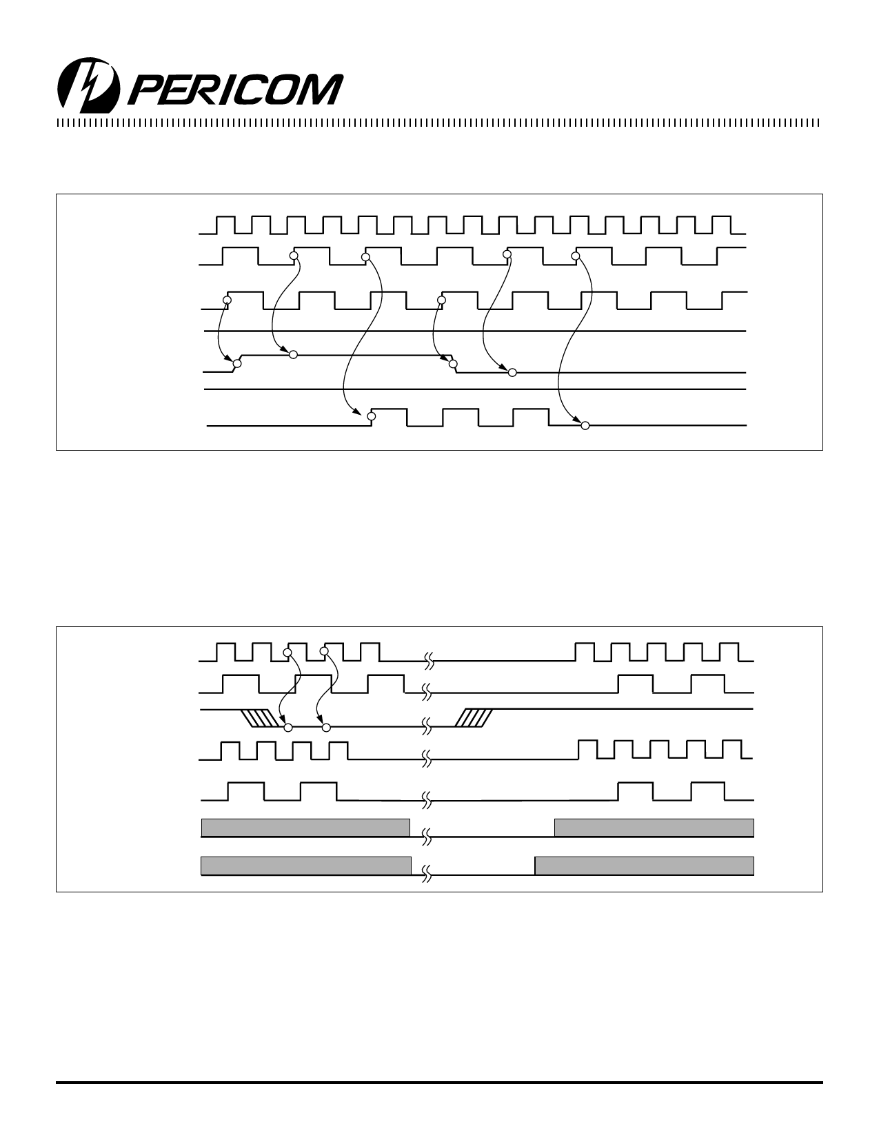
PCI_STOP# is an input signal used to turn off PCI clocks for low started with a guaranteed full high pulse width. There is ONLY one
power operation. PCI clocks are stopped in the LOW state and rising edge of external PCICLK after the clock control logic.
CPUCLK
(Internal)
PCICLK
(Internal)
PCICLK_F
(Free-running)
CPU_STOP#
PCI_STOP#
PWR_DWN#
PCICLK
(External)
PCI_STOP# Timing Diagram
Notes:
1. All timing is referenced to the CPUCLK.
2. PCI_STOP# signal is an input signal which must be made synchronous to PCI_F output.
3 Internal means inside the chip.
4. All other clocks continue to run undisturbed.
5. PWR_DWN# and CPU_STOP# are shown in a high state.
6. Diagrams shown with respect to 66MHz. Similar operation as CPU = 100 MHz.
CPUCLK
(Internal)
PCICLK
(Internal)
PWR_DWN#
CPUCLK
(External)
PCICLK
(External)
VCO
Crystal
Notes:
PWR_DWN# Timing Diagram
1. All timing is referenced to the CPUCLK.
2. The Internal label means inside the chip and is a reference only.
3. PWR_DWN# is an asynchronous input and metastable conditions could exist. The signal is synchronized inside the part.
4. The shaded sections on the VCO and the Crystal signals indicate an active clock.
5. Diagrams shown wth respect to 66 MHz. Similar operation as CPU = 100 MHz.
4
P8399-1 06/11/99
Share Link: 