DS1213B データシートの表示(PDF) - Dallas Semiconductor -> Maxim Integrated
部品番号
コンポーネント説明
一致するリスト
DS1213B Datasheet PDF : 7 Pages
| |||
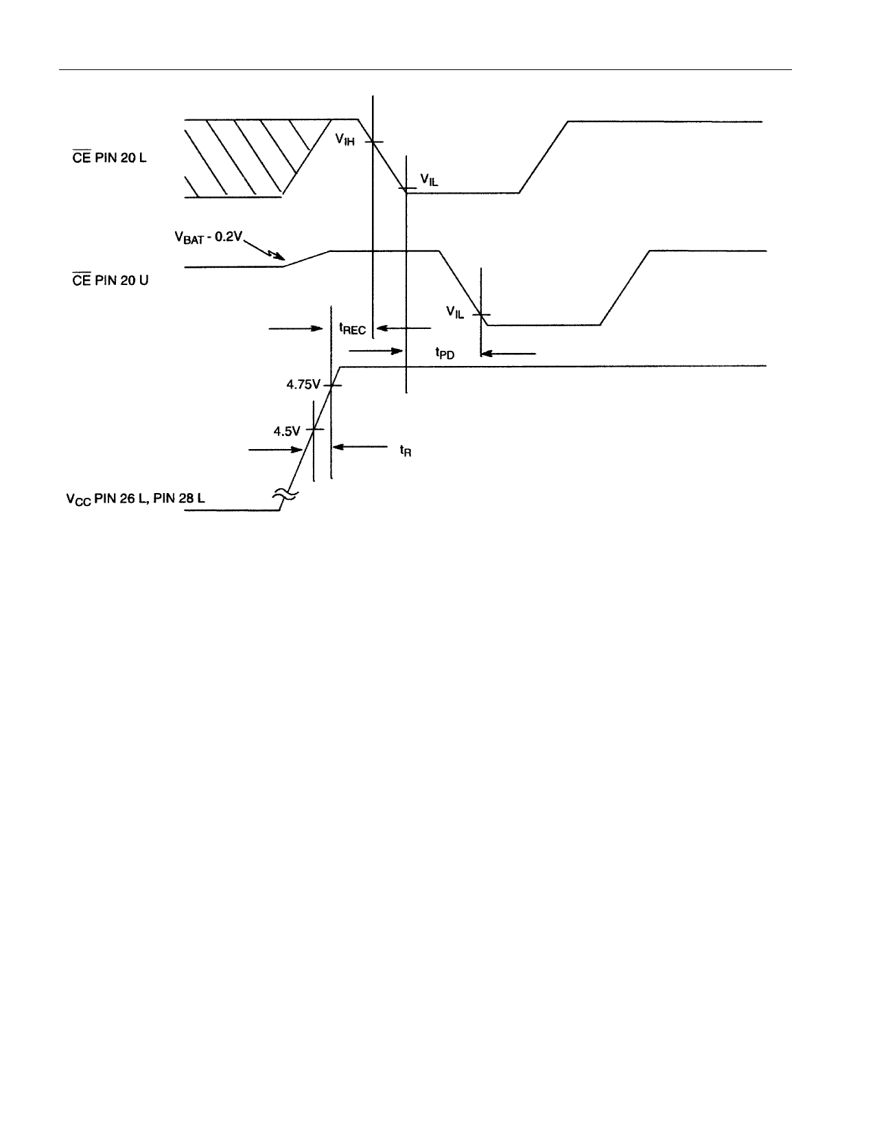
TIMING DIAGRAM: POWER-UP
DS1213B
WARNINGS:
Under no circumstances are negative undershoots, of any amplitude, allowed when device is in battery
backup mode.
Water washing for flux removal will discharge internal lithium source because exposed voltage pins
are present.
NOTES:
1. All voltages are referenced to ground.
2. Measured with a load as shown in Figure 1.
3. Pin locations are designated “U” (for upper) when a parameter definition refers to the socket
receptacle and “L” (for lower) when a parameter definition refers to the socket pin.
4. No memory inserted in the socket.
5. Pin 26 L may be connected to VCC or left disconnected at the PC board.
6. IBAT is the maximum load current which a correctly installed memory can use in the data retention
mode and meet data retention expectations of more than 10 years at 25°C.
7. tCE max. must be met to ensure data integrity on power loss.
8. VCC is within nominal limits and a memory is installed in the socket.
9. Input pulse rise and fall times equal 10 ns.
5 of 7
Share Link: 