USS344 データシートの表示(PDF) - Agere -> LSI Corporation
部品番号
コンポーネント説明
一致するリスト
USS344 Datasheet PDF : 54 Pages
| |||
Advance Data Sheet, Rev. 9
June 2001
USS-344 QuadraBus
Four-Host PCI-to-USB OpenHCI Host Controller
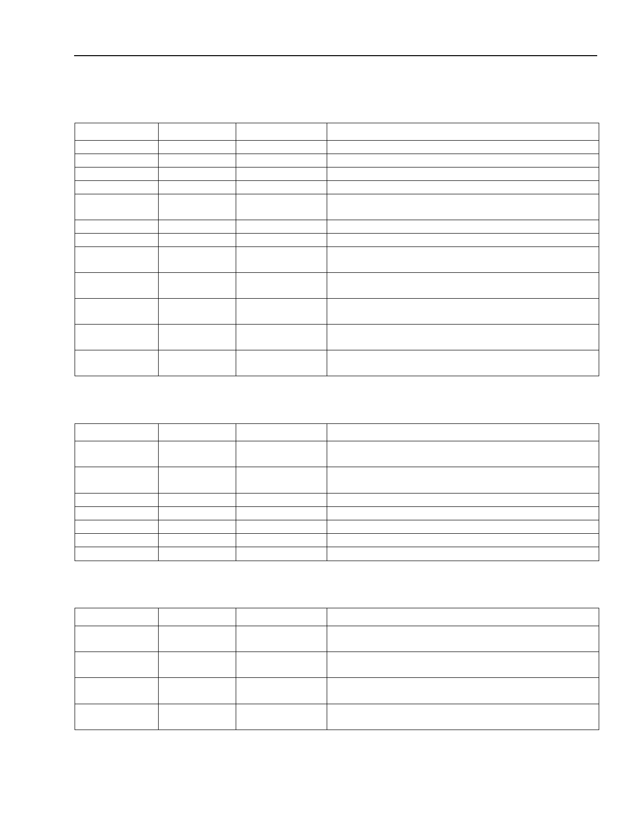
Pin Information (continued)
Table 3. USB Port Signals (continued)
Pin
77
79
102
104
81
87, 93, 99
88, 94, 100
86
85
82
84
83
Symbol*
PWRFLT0N
PWRFLT1N
PWRFLT2N
PWRFLT3N
CLK48STOP
VDDT
VSST
RREF
VDDA
VSSA
XHI
XLO/CLK48
Type
Input
Input
Input
Input
Bidir
Power
Power
Input
Power
Power
Power
Power/Input
Description
USB Port 0 Overcurrent (Active-Low).
USB Port 1 Overcurrent (Active-Low).
USB Port 2 Overcurrent (Active-Low).
USB Port 3 Overcurrent (Active-Low).
USB Clock Stop (Optional). Used to stop external
48 MHz clock in PCI power management state D3.
USB Transceiver VDD (3.3 V).
USB Transceiver VSS.
USB 2.0 1 kΩ Precision Resistor Connection. Hi-Z if
implementation does not expect upgrade to USB 2.0.
USB 2.0 Analog Power. Connect to VDD if implementa-
tion does not expect upgrade to USB 2.0.
USB 2.0 Analog Power. Connect to VSS if implementa-
tion does not expect upgrade to USB 2.0.
USB 2.0 Crystal Oscillator XHI Connection. Hi-Z if
implementation does not expect upgrade to USB 2.0.
USB 2.0 Crystal Oscillator XHI Connection/USB 1.X
CLK 48 MHz Input.
* An N following the symbol names indicates active-low for the USS-344.
Table 4. Legacy Support Signals
Pin
Symbol*
Type
Description
68
KIRQ1I
Input
Legacy Keyboard Controller Interrupt (IRQ1 Input from
Keyboard Controller).
67
MIRQ12I
Input
Legacy Mouse Controller Interrupt (IRQ12 Input from
Mouse Controller).
69
A20I
Input
Legacy Gate A20 Input.
70
A20MN Output/Open Drain Legacy Gate A20 Output (to Memory Controller).
71
IRQ1
Output/Open Drain System Keyboard Interrupt (Active-High).
72
IRQ12
Output/Open Drain System Mouse Interrupt (Active-High).
75
SMIN
Output/Open Drain System Management Interrupt (Active-Low).
* An N following the symbol names indicates active-low for the USS-344.
Table 5. Chip Test Signals
Pin
Symbol*
Type
Description
61
TEST0
Input
Chip Test Signal. Refer to Test Mode Connection
Instructions section for usage information.
62
TEST1
Input
Chip Test Signal. Refer to Test Mode Connection
Instructions section for usage information.
63
TEST2
Input
Chip Test Signal. Refer to Test Mode Connection
Instructions section for usage information.
64
TEST3
Input
Chip Test Signal. Refer to section Test Mode Connection
Instructions for usage information.
* An N following the symbol names indicates active-low for the USS-344.
Agere Systems Inc.
7
Share Link: 