MSM66P54-04 データシートの表示(PDF) - Oki Electric Industry
部品番号
コンポーネント説明
一致するリスト
MSM66P54-04 Datasheet PDF : 22 Pages
| |||
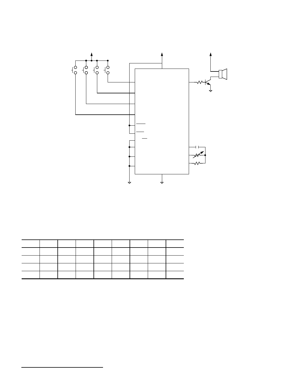
s MSM66P54 OTP Speech Synthesizer s––––––––––––––––––––––––––––––––––––––––––––––––––––––––––
S4 S3 S2 S1
SW0
SW1
SW2
SW3
TEST
RND
XT/RC
A0
A1
A2
VDD
GND
AOUT
OSC3
OSC2
OSC1
Figure 8. Application Circuit in Standalone Mode
with Parallel Input Interface
The following table shows a comparison between switches and speech playback addresses.
Switches and Speech Playback Address Comparison
A2
A1
A0
SW3 SW2 SW1 SW0 ADR
S1
0
0
0
0
0
0
1
01
S2
0
0
0
0
0
1
0
02
S3
0
0
0
0
1
0
0
04
S4
0
0
0
1
0
0
0
08
4-10
OKI SEMICONDUCTOR
Share Link: 