M74HC393(1993) データシートの表示(PDF) - STMicroelectronics
部品番号
コンポーネント説明
一致するリスト
M74HC393 Datasheet PDF : 12 Pages
| |||
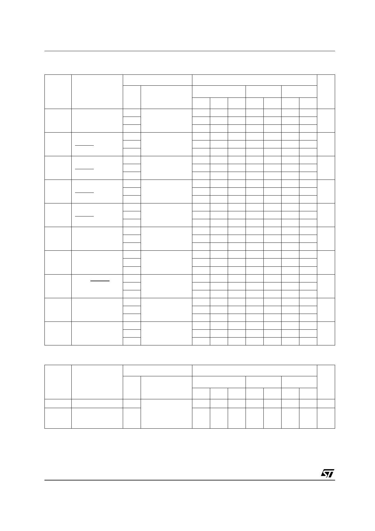
M54/M74HC393
AC ELECTRICAL CHARACTERISTICS (CL = 50 pF, Input tr = tf = 6 ns)
Symbol
Parameter
Test Conditions
VCC
(V)
TA = 25 oC
54HC and 74HC
Value
-40 to 85 oC -55 to 125 oC Unit
74HC
54HC
Min. Typ. Max. Min. Max. Min. Max.
tTLH Output Transition 2.0
tTHL Time
4.5
30 75
8
15
95
110
19
22
ns
6.0
7
13
16
19
tPLH Propagation
2.0
tPHL Delay Time
4.5
(CLOCK - QA)
6.0
50 120
150
180
15 24
30
36
ns
13 20
26
31
tPLH Propagation
2.0
tPHL Delay Time
4.5
(CLOCK - QB)
6.0
70 160
200
240
20 32
40
48
ns
17 27
34
41
tPLH Propagation
2.0
tPHL Delay Time
4.5
(CLOCK - QC)
6.0
90 195
245
295
25 39
49
59
ns
21 33
42
50
tPLH Propagation
2.0
tPHL Delay Time
4.5
(CLOCK - QD)
6.0
120 230
290
345
30 46
58
69
ns
26 39
49
59
tPLH Propagation
2.0
tPHL Delay Time
4.5
(CLEAR - Qn)
6.0
55 150
190
225
18 30
38
45
ns
15 26
32
38
fMAX Maximum Clock 2.0
Frequency
4.5
8.4 17
6.8
5.6
42 67
34
28
MHz
6.0
50 79
40
33
tW(H) Minimum Pulse
2.0
tW(L) Width
4.5
(CLOCK)
6.0
28 75
7
15
6
13
95
110
19
22
ns
16
19
tW(H) Minimum Pulse 2.0
Width
4.5
(CLEAR)
6.0
28 75
7
15
6
13
95
110
19
22
ns
16
19
tREM Minimum
2.0
Removal Time
4.5
25
30
35
5
6
7
ns
6.0
5
5
6
CIN Input Capacitance
5
10
10
10 pF
CPD (*) Power Dissipation
35
Capacitance
pF
(*) CPD is defined as the value of the IC’s internal equivalent capacitance which is calculated from the operating current consumption without load.
(Refer to Test Circuit). Average operting current can be obtained by the following equation. ICC(opr) = CPD •VCC •fIN + ICC/4 (per Flip Flop)
6/12
Share Link: 