ICS9219 データシートの表示(PDF) - Integrated Circuit Systems
部品番号
コンポーネント説明
一致するリスト
ICS9219 Datasheet PDF : 8 Pages
| |||
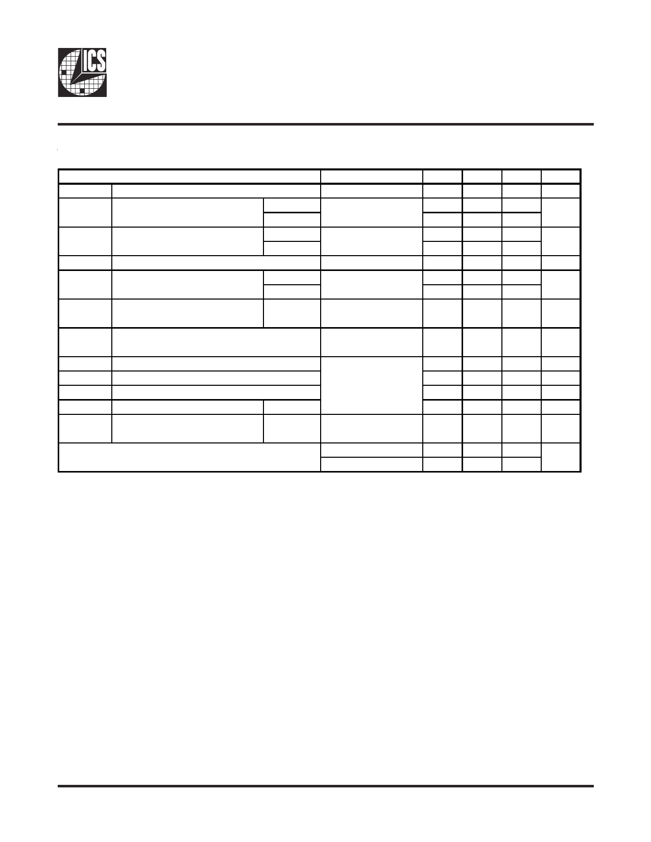
ICS9219
Switching Characteristics over Recommended Operating Free-Air Temperature Range.
t(CYCLE)
tJ
tJL
DC
tDC,ERR
PARAMETER
Clock cycle time (BUSCLKT/C)
Total jitter over 1, 2, 3, 4, 5 or 6 clock
cycles
400 MHz
533 MHz
Long-term jitter
400 MHz
533 MHz
Output duty cycle over 10,000 cycles
Output cycle-to-cycle duty cycle error
400 MHz
533 MHz
TEST CONDITIONS*
See Figure 3
See Figure 4
See Figure 5
See Figure 6
MIN
1.8
43%
TYP**
42
33
51
30
30
MAX
3.7
50
50
300
300
53%
50
50
UNIT
ns
ps
ps
ps
tCR, tDF
Output rise and fall times (measured at BUSCLKT/C
20%-80% of output voltage)
See Figure 7
120
250
400
ps
Difference between rise and fall times on a single
∆tRF
device (20% ± 80%) |tCR - tCF|
See Figure 7
50
100
ps
tCYCLE(L)
t(CJ)
t(CJ10)
DC(2)
tCRL, tCFL
Clock cycle time (REF)
REF cycle jitter
REF 10-cycle jitter
Output duty cycle
Output rise and fall times (measured at
20%-80% of output voltage)
REF
REF
80
142.2
ns
See Figure 8
-0.2
0.1
0.2
ns
Measured at 50%
-1.3 t(CJ)
1.3 t(CJ)
ns
47%
50
53%
See Figure 7
0.8
1
ns
PLL loop bandwidth
fmod = 50 kHz
fmod = 8 MHz
-20
-3
dB
0931B—10/25/04
5
Share Link: 