BA6906F データシートの表示(PDF) - ROHM Semiconductor
部品番号
コンポーネント説明
一致するリスト
BA6906F Datasheet PDF : 4 Pages
| |||
2/3
〇ELECTRICAL CHARACTERISTICS (Unless otherwise specified Ta=25℃,Vcc=5V)
Parameter
Symbol
Min.
Limit
Typ.
Max.
Unit
Conditions
Circuit current
Icc
1.5 3.4 8.7 mA At output OFF
Charge current of capacitor
for lock detection
ILDC 1.50 2.75 4.50 μA VLD=1.1V
Discharge current of capacitor for
lock detection
ILDD
0.24 0.48 0.90 μA VLD=1.1V
Charge-discharge current ratio of
capacitor for lock detection
rCD
4.2 5.7 9.5
- rCD=ILDC/ILDD
Clamp voltage of capacitor
for lock detection
VLDCL 1.14 1.80 2.47 V
Comparison voltage of capacitor
for lock detection
VLDCP 0.47 0.76 1.06
V
Output voltage L
VOL
-
0.2
0.3
V Io=200mA
Output voltage H
VOH 3.9 4.1
-
V Io=-200mA
FG terminal voltage L
VALL
-
0.3
0.5
V IAL=5mA
FG terminal leak current
IALL
-
0
50 μA VAL=15V
Hall input offset voltage
Hofs -10
-
10 mV
Hall input-output gain
GHO 320 500 680
-
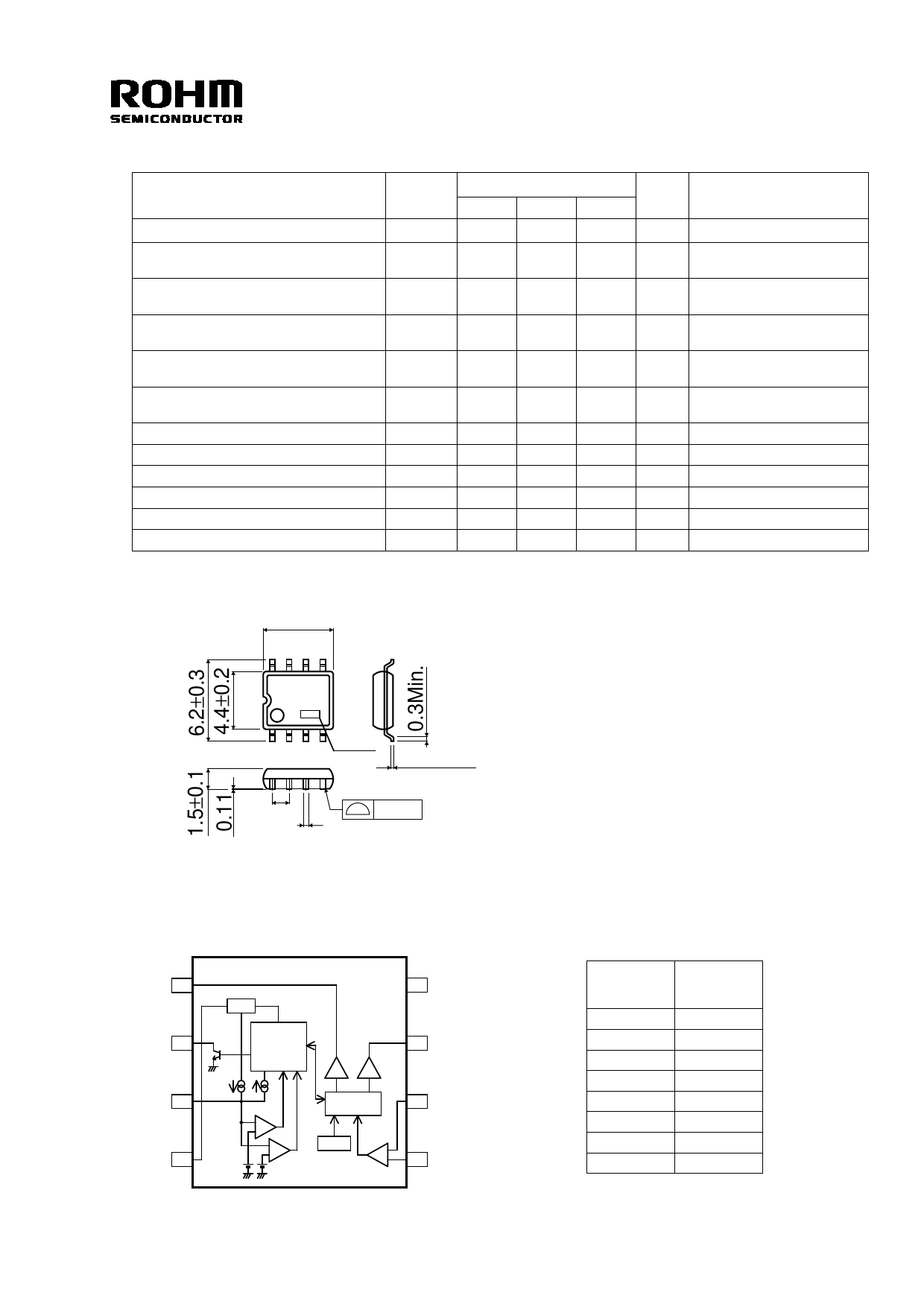
〇PACKAGE OUTLINES
5.0±0.2
85
6906
1
4 Lot No. 0.15±0.1
1.27
0.1
0.4±0.1
SOP 8(UNIT:mm)
〇BLOCK DIAGRAM
〇Terminal name
OUT2
1
AL
2
LD
3
Vcc
4
REG
LOCK
DETECTION
AND
AUTO
RESTART
+
-
+
-
GND
8
OUT1
7
H-
Control
6
HALL
TSD
AMP -
H+
+
5
Pin No.
1
2
3
4
5
6
7
8
Terminal
name
OUT2
AL
LD
Vcc
H+
H-
OUT1
GND
REV. D
Share Link: 